
3d part design with Inkscape and Openscad part 2: Designing a simple object
I will be going through the set up for the customizer, but to keep it simple here is a link to the OpenScad file that already has the customizer set up, it's still a work in progress as I am working on the union and difference boolean stuff.
https://www.dropbox.com/s/jxdoif3l0lr047m/Inkscape2Openscad1.scad?dl=0
Designing an object in Inkscape: I will make a simple box to show how to make a design, what settings need to be used and how to export it to the OpenScad file that I posted above so it can be modified and converted to an .stl file.
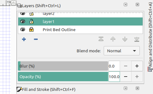
First I make sure that "layer1" is selected so that the bottom of the box is drawn on that layer:
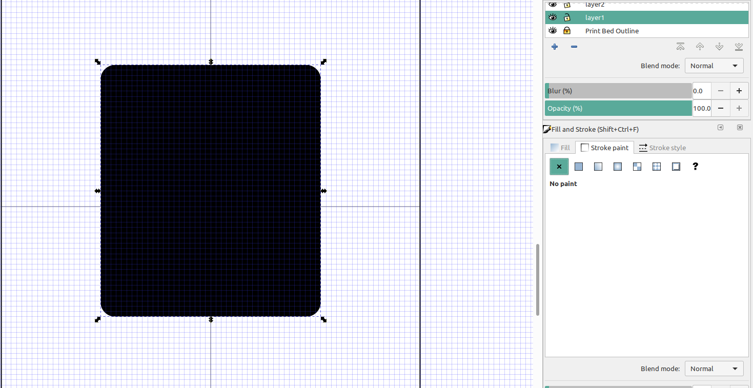
I'm going to set the infill to a solid color and turn off the stroke:
Next I will copy this square and paste it on "layer2", turn off the fill, turn on the stroke and make it a different color:
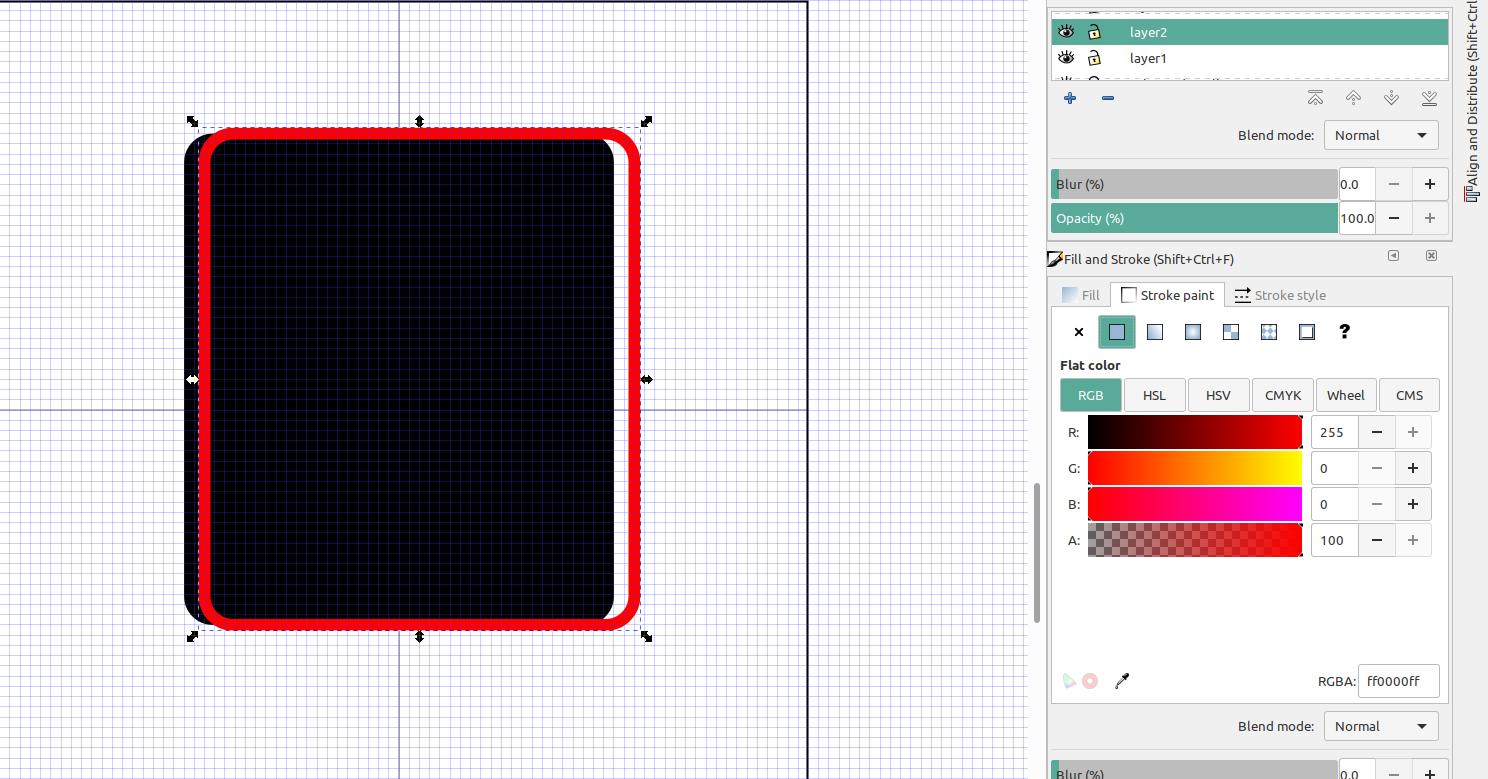
And center the two objects so that they are aligned:
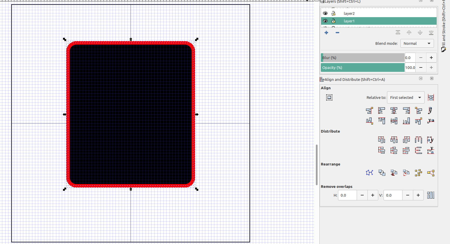
Now the bottom of my box is on layer 1, the sides of the box will be on layer 2.
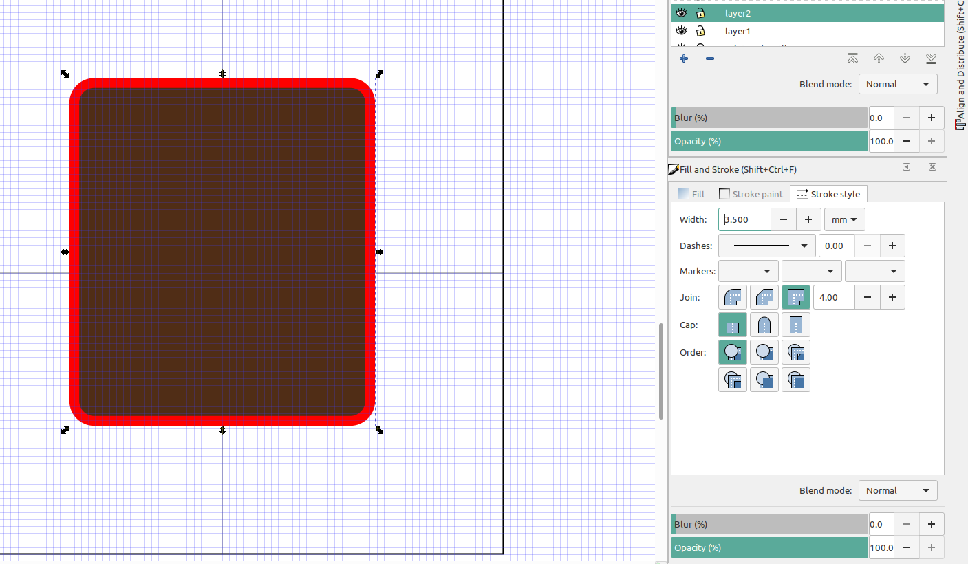
I always make the walls of my boxes a little thicker and it's easy to set the stroke width to what ever thickness you want:
Next select all of the objects and convert them to paths, make sure both layers are selected then goto Path>object to path, and then path> stroke to path
Next add multiple nodes to the paths and then convert them to lines, the more nodes there are the finer the details will be in the print, but on a slower computer it will take a lot longer to process so I would only add a few extra nodes if you have a slower computer:
Sometimes the the two paths don't convert to lines properly and you will get a spline error in OpenScad, so you may need to separate them, convert them to lines, then re-center them:
Now the box is ready to be exported to Openscad, hide the print bed layer and export to AutoCad dxf R14, name the file, click use LWPOLYLINE output, character UTF8, and visible only:

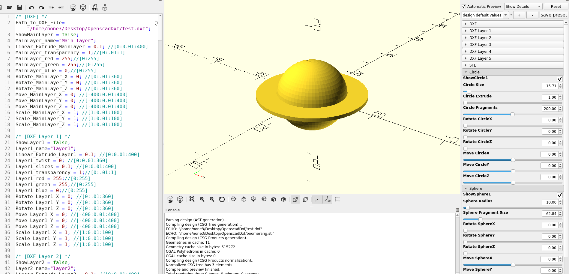
Next open the file in OpenScad by entering the path to the file, select the layers you want to show and extrude them to the proper height:
At first this might seem like a complicated process, but after you do it a couple of times is really easy, and you can make just about anything you can imagine pretty quickly.
Part 3 will go more in depth and I will cover more detail on setting up the customizer in OpenScad.