
3D part design with Inkscape and OpenSCAD #95: Design a custom 3d printed shoe sole.
This is post #2 of a series where I will be designing custom shoes that can be 3d printed, in the last post I made a module for OpenSCAD that I could use to make the top part of a shoe.
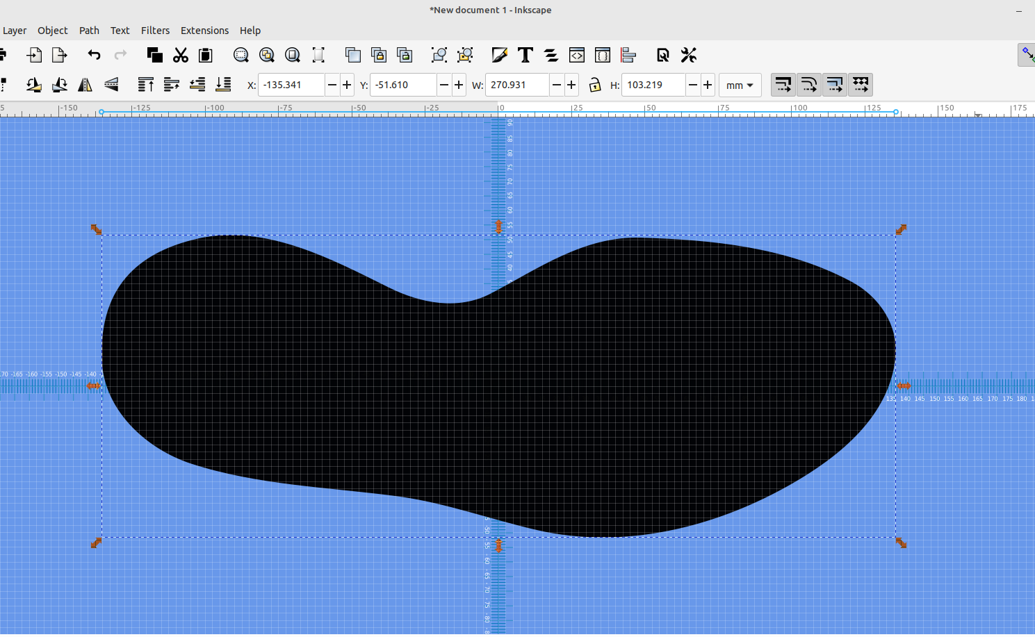
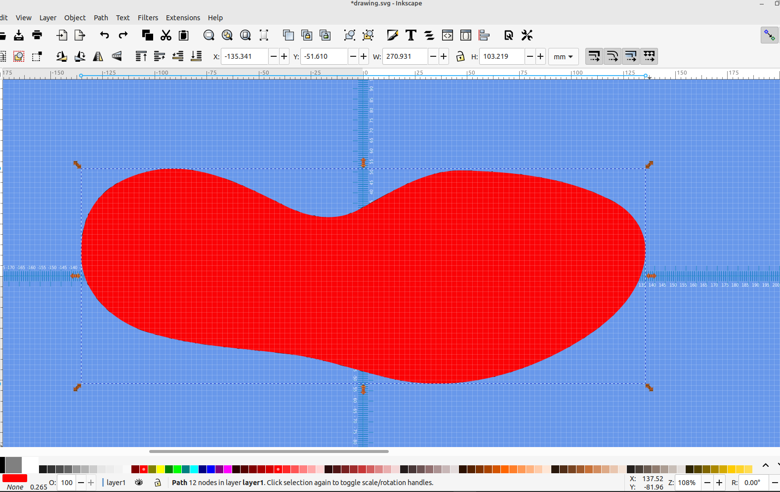
The first step is to import the outline of the shoe sole into Inkscape, it's pretty easy to make one that will custom fit your foot with a scanner, or you can just find a basic shape to use:
Next decide what you want the tread pattern to be, I used the InfinityPlays website logo:
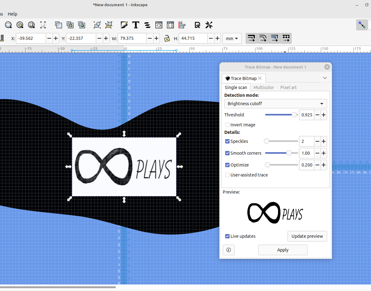
Once I had the logo imported I went to Path> Trace Bitmap, set the threshold and traced the logo.
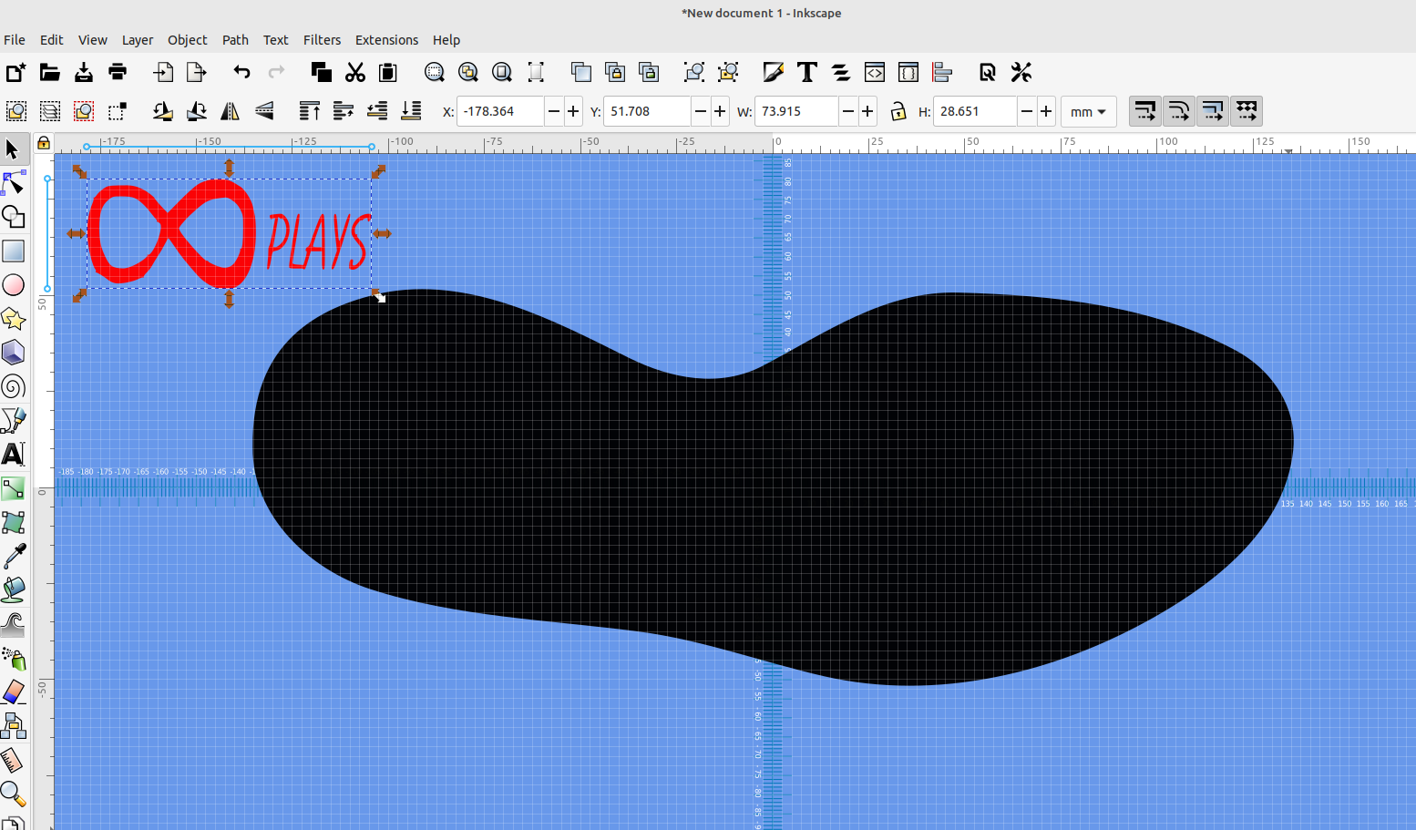
Now that I have a trace of my image I deleted the picture I had imported and set the traced image off to the side.
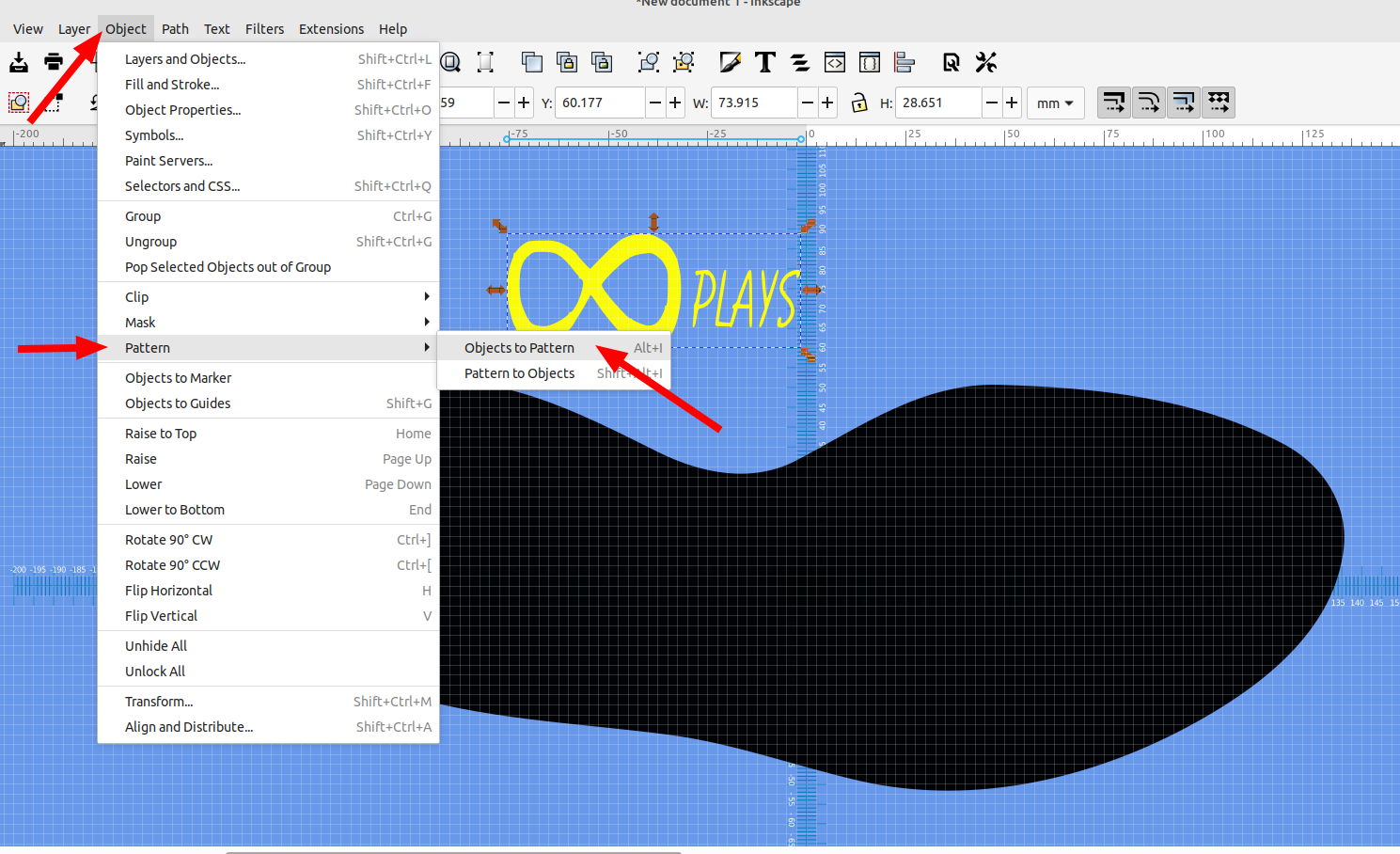
Now select the traced image and goto Object>Pattern>Object to Pattern.
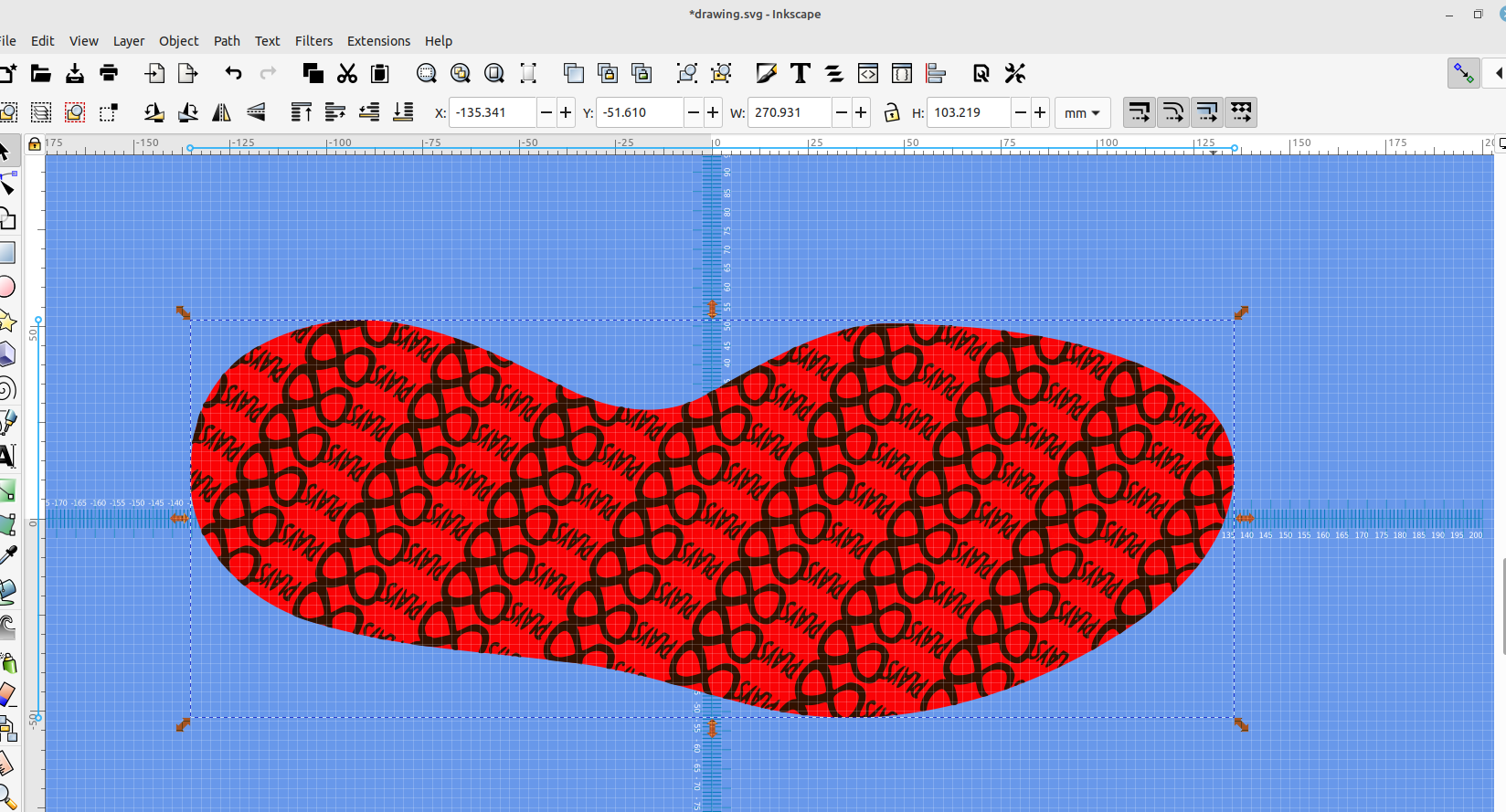
This will make the object available in the fill and stroke dialog so we can fill our sole outline with it:
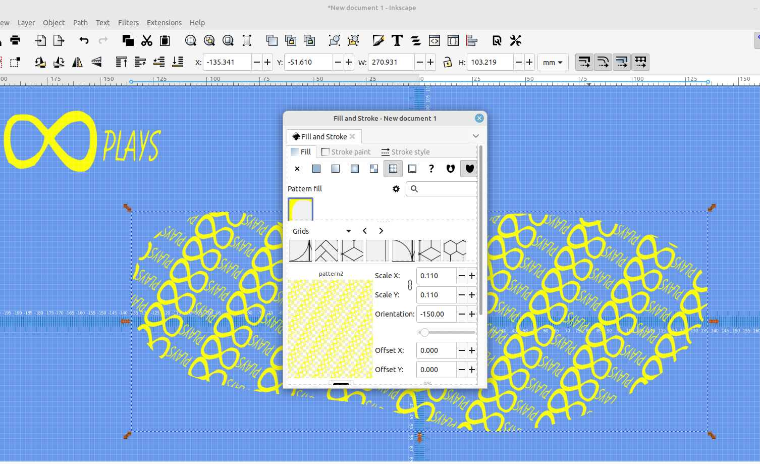
Now you can adjust the size and orientation of the pattern.
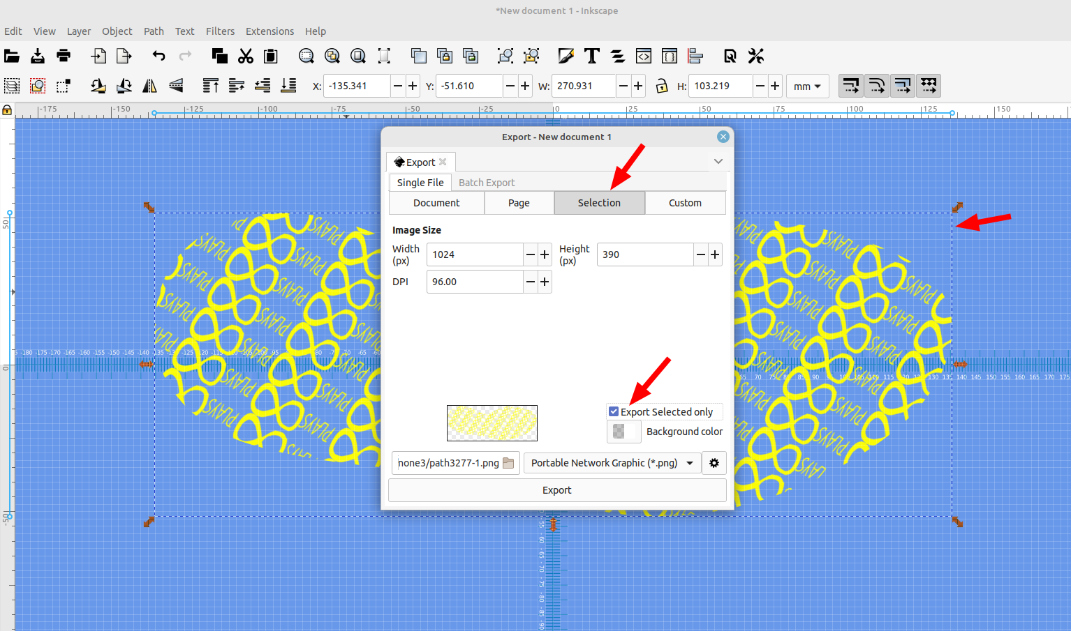
Next delete the traced image that was set off to the side and goto File>Export> and select "Selection" and "Export selection only", this will give us a .png file of our tread design that we will trace again,unfortunately this step is necessary because Inkscape won't allow a pattern fill to be converted to a vector object for some reason, hopefully that option is added in a new version .
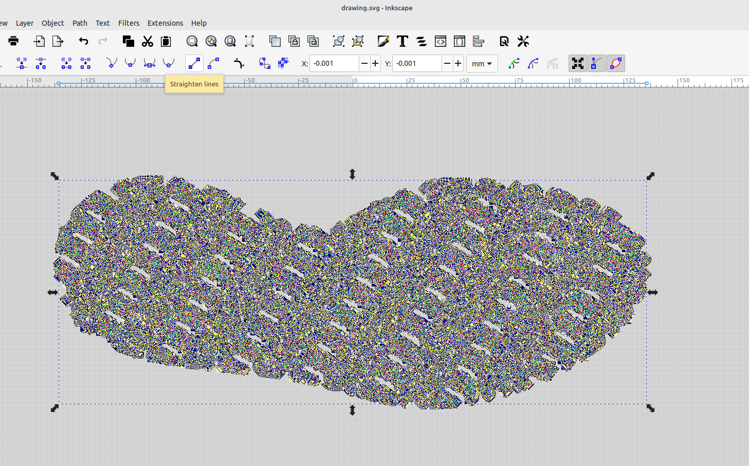
Next import the .png file that was saved and trace it with Path>Trace Bitmap.
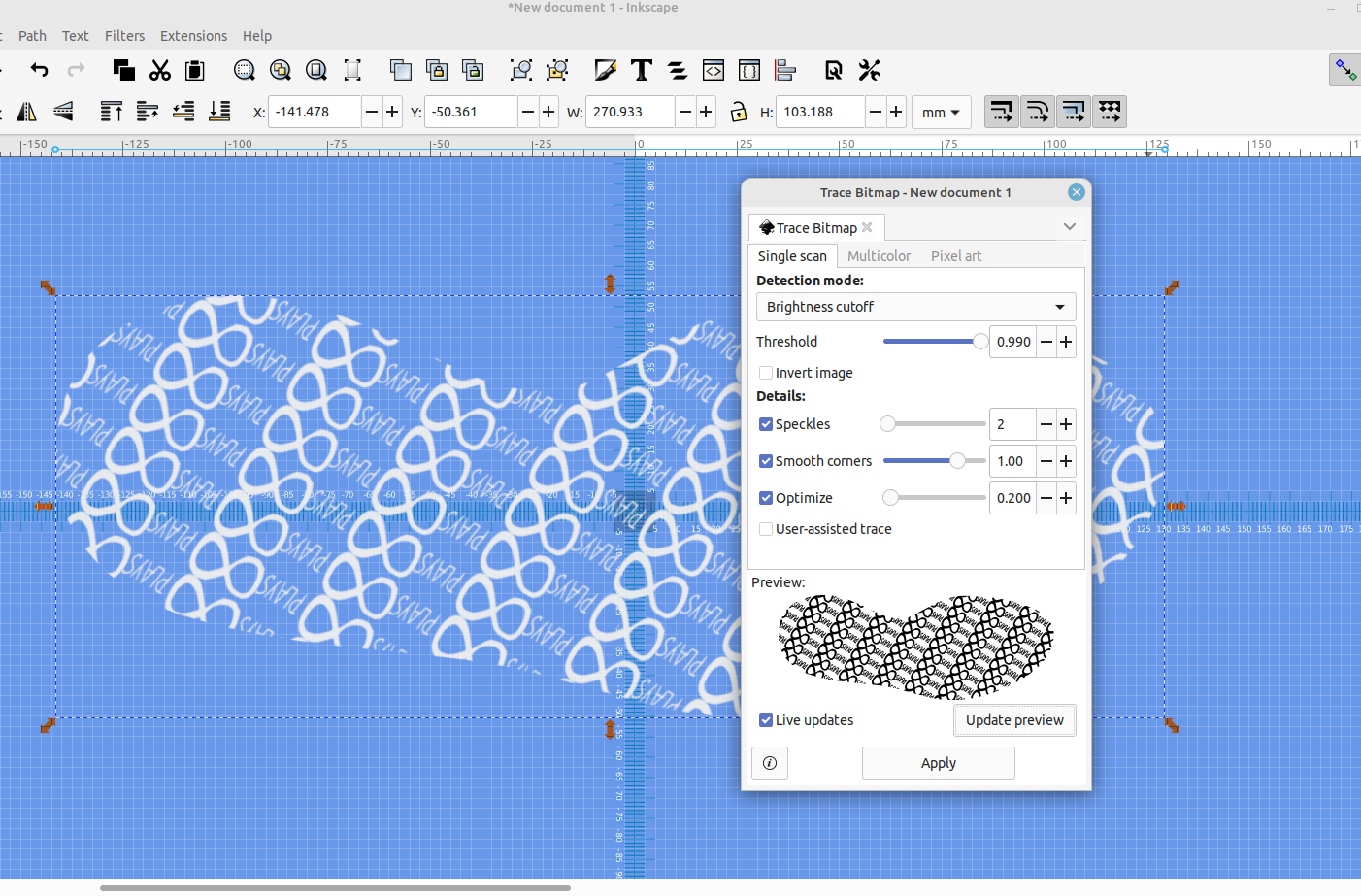
Now we can keep the traced pattern and delete the fill pattern one.
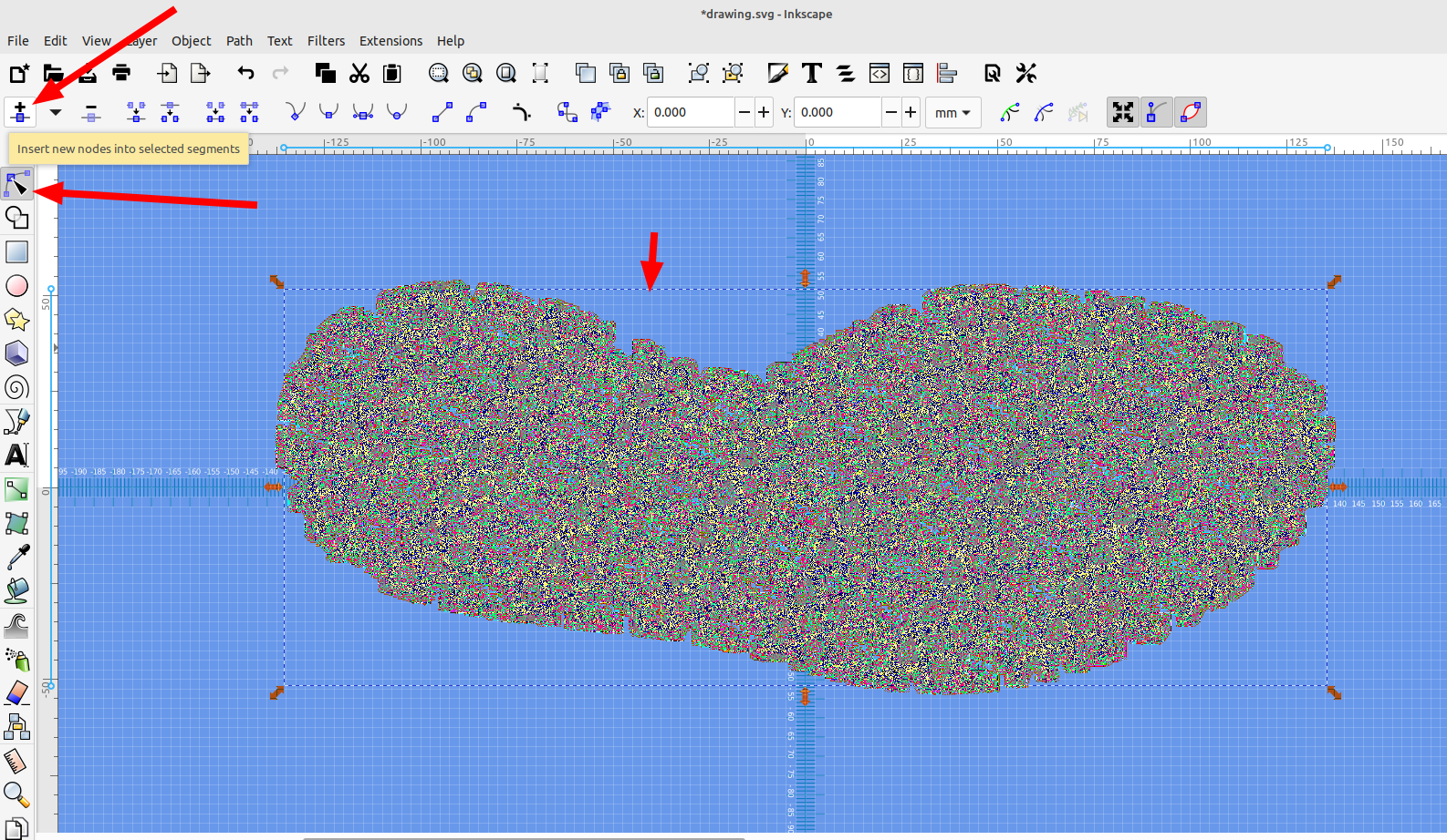
Then select the traced image and select Node tools and click on "add new nodes" three times, then "straighten lines" this will give the design better detail and will make it render way faster in OpenSCAD, the new manifold option handles bezier curves in an svg file but with a complex object like this it will take along time to render.
Now we will import the basic sole shape again and move it to layer 2 :
Now the sole shape should be on layer 2 and the tread pattern on layer 1
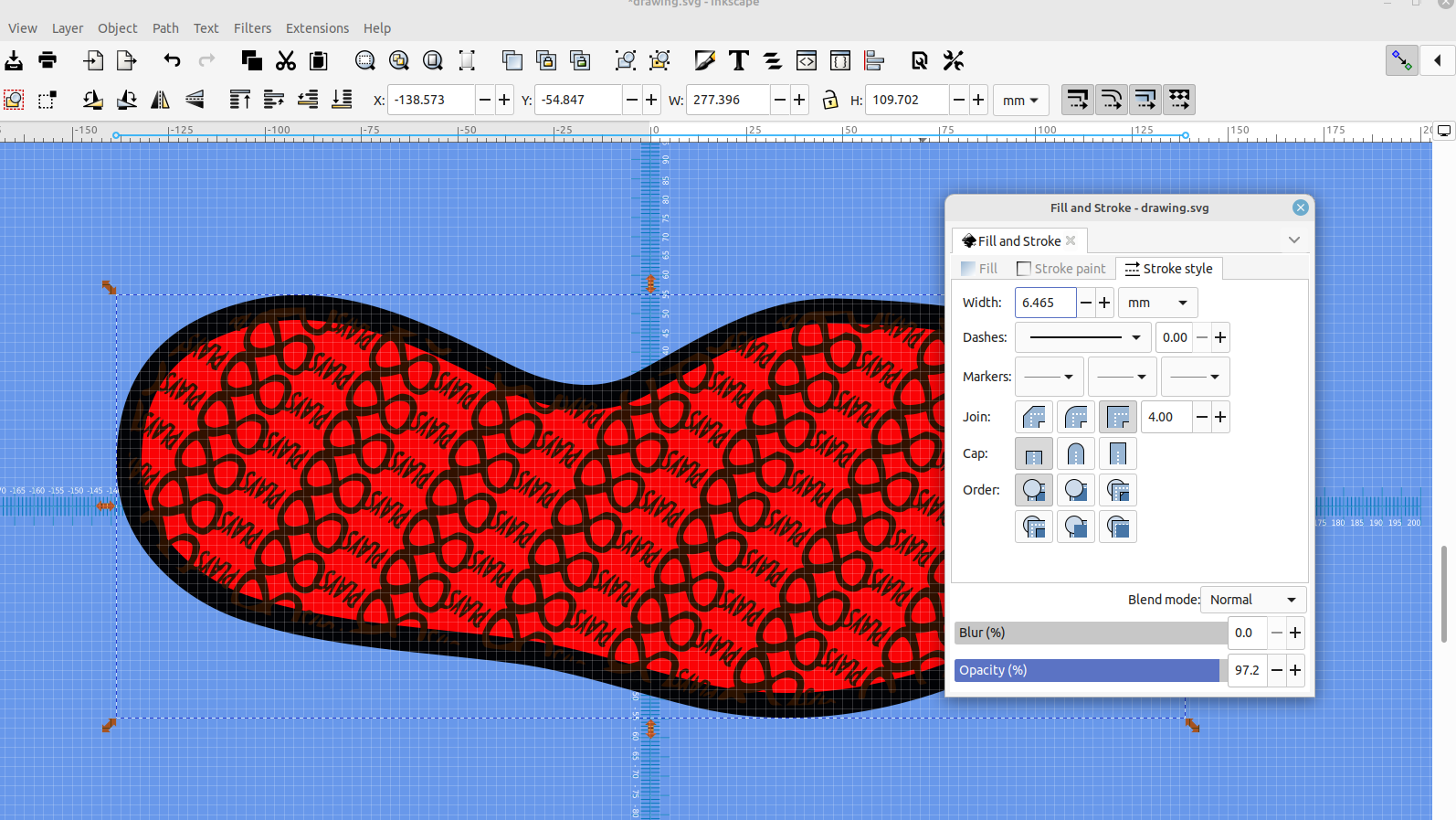
Open the fill and stroke dialog for the sole outline, turn on the stroke and set the stroke width:
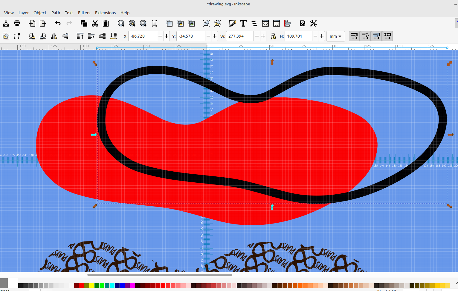
now goto Path> and click "Object to path" Then "stroke to path" this will allow us to double click on the sole outline, separate the stroke outline and move it to layer 3:
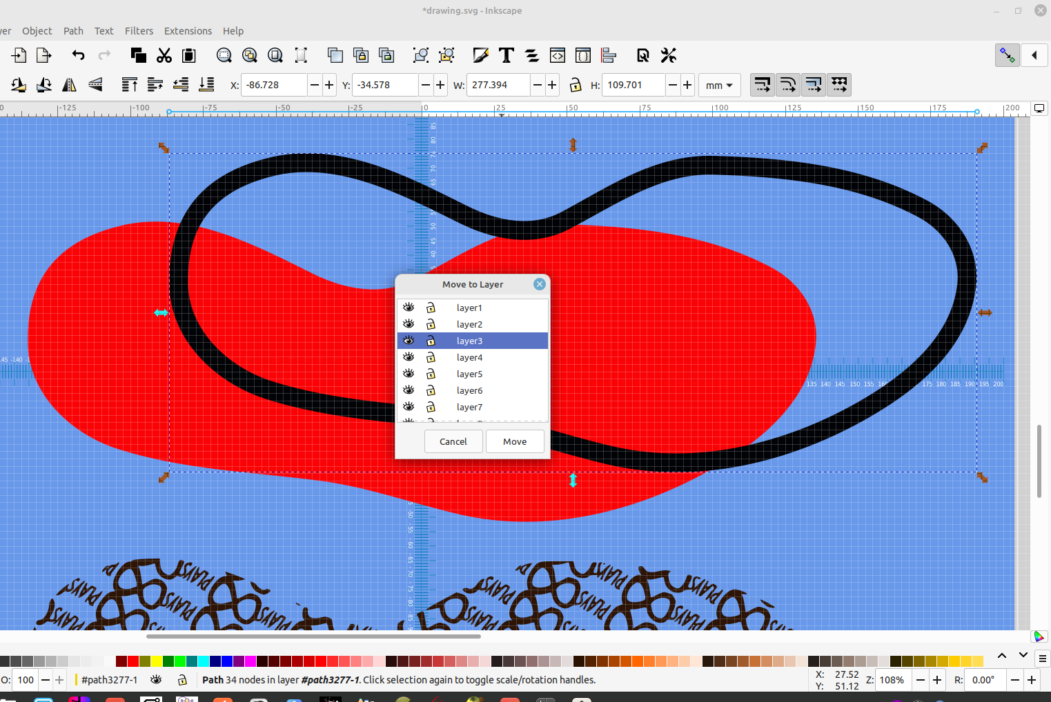
Now we have the tread pattern on layer1, the sole shape on layer 2, and the sole outline on layer 3 and can align all three so they are centered with each other then save the image as an Inkscape svg to import into OpenSCAD
In post #68 I made an OpenSCAD example for importing multiple svg layers.
 Bob
Bob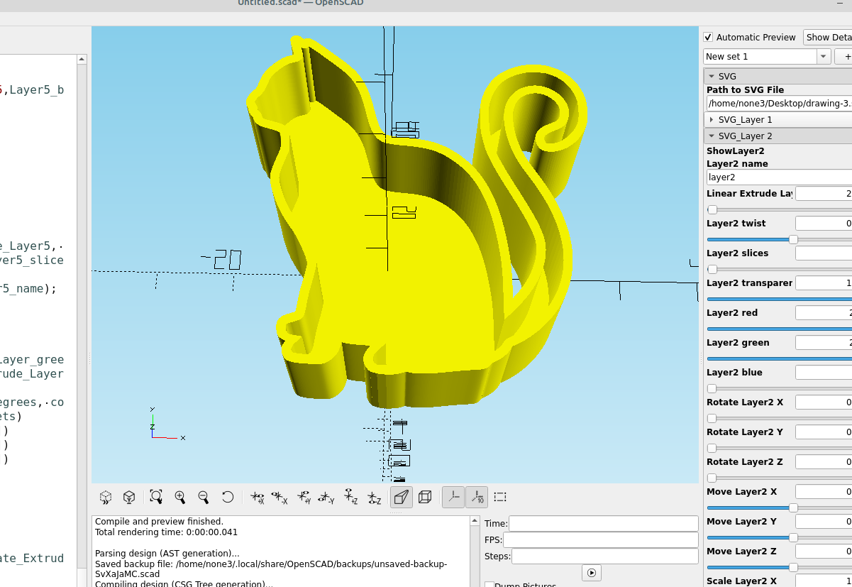
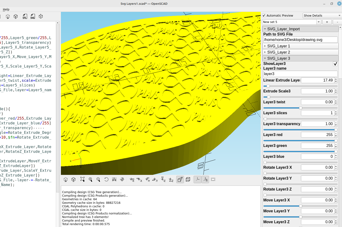
Now the saved svg file can be imported into OpenSCAD and the layers adjusted to the desired heights:
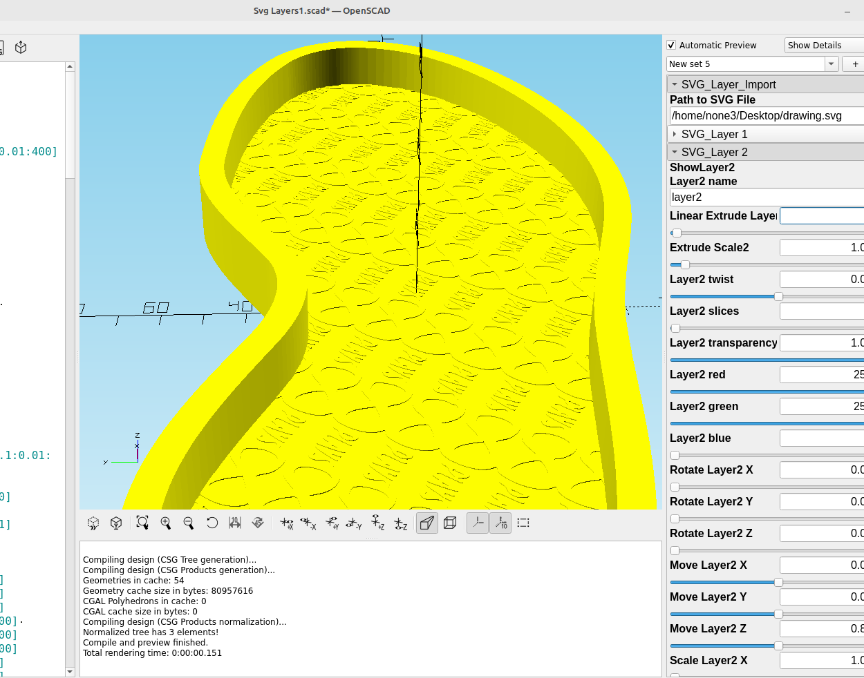
This might seem like a long process but it is actually pretty fast and easy once you have it down.