Easy pcb isolation milling with Kicad and Inkscape gcodetools extension.
Over the years I have used several different programs to mill printed circuit boards with a cnc and there are some excellent options like Flatcam that work great and are well worth learning, here is another option that also works really well, 100% opensource, and is pretty easy for beginners.
I have detailed how to make a pcb with Kicad in other posts and I am assuming you already have a board designed.
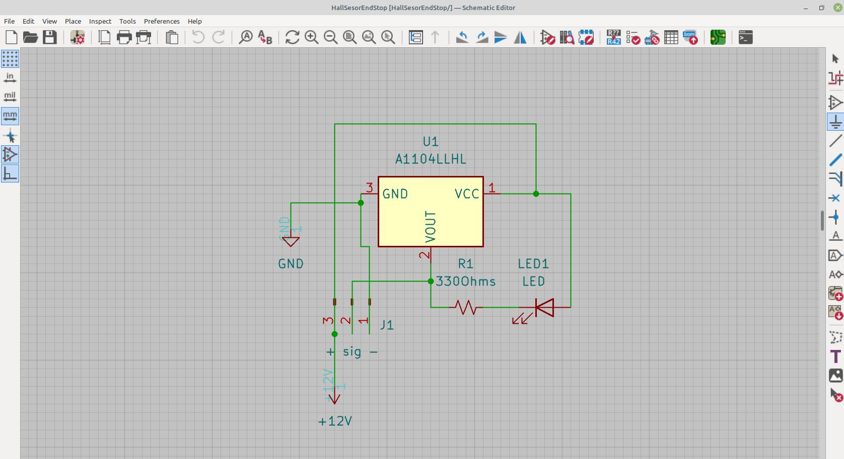
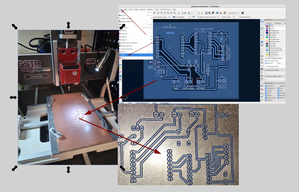
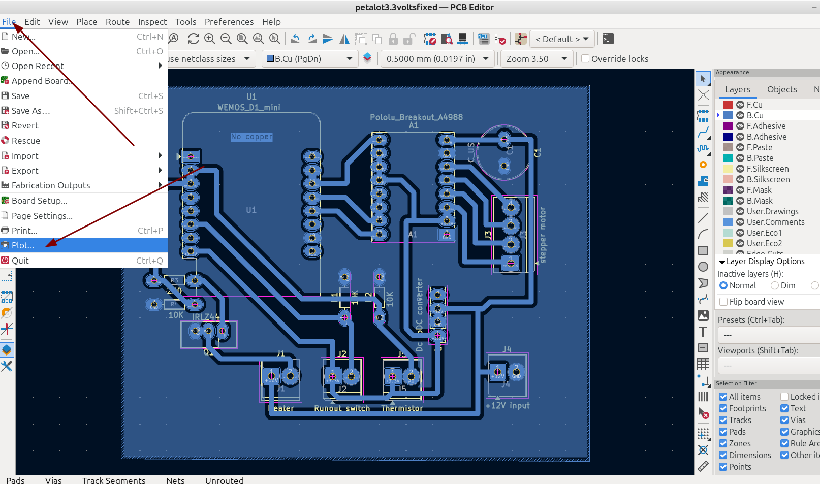
Once you have your board ready in Kicad export it as an svg by going to File>Plot:
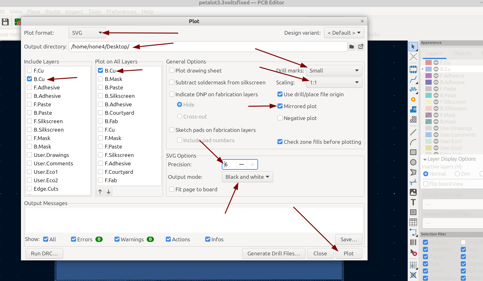
A dialog will pop up and you can set the options for the layers you want to plot, here is a screenshot of the settings I use for this post : (click on the picture for a larger version)
Now that you have the file saved you can open it with Inkscape. I have also made a post on using layers in Inkscape for gcode tools but I will cover most of how to do it again in this post :
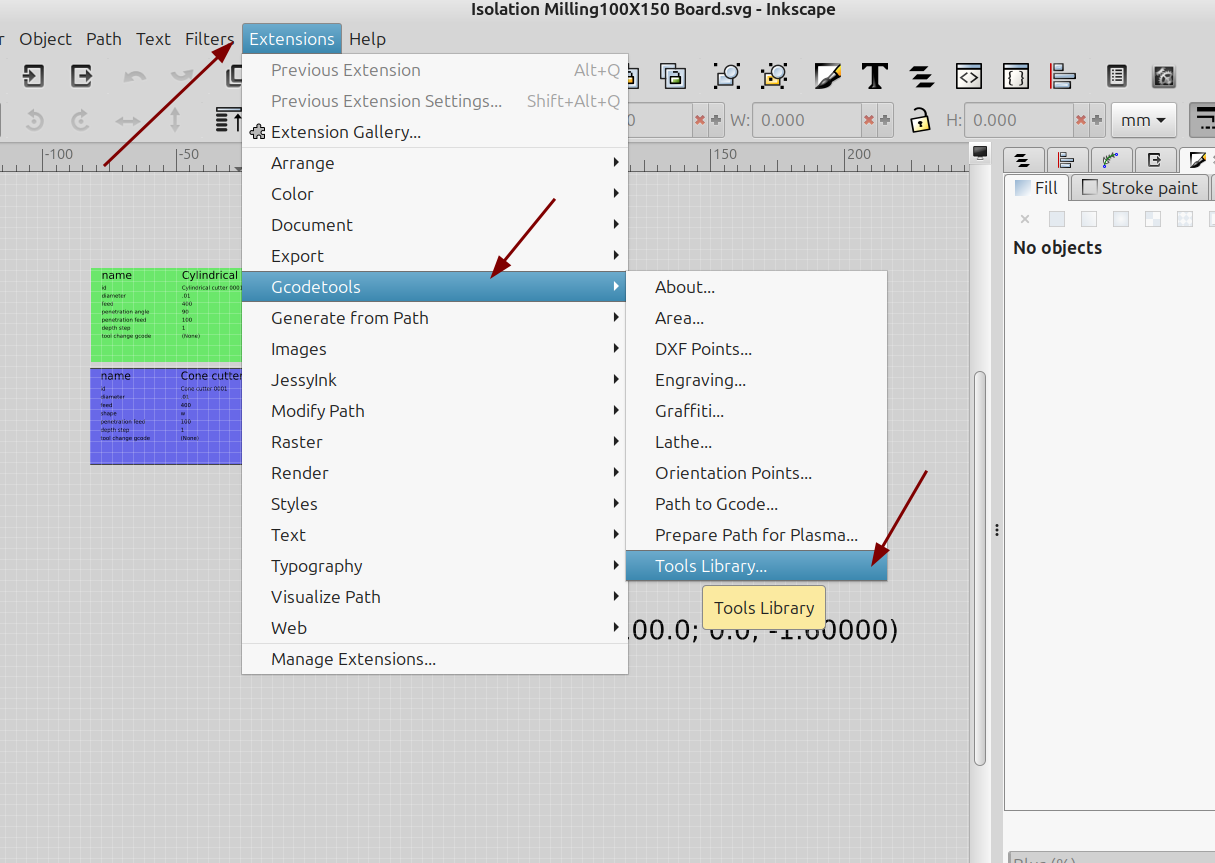
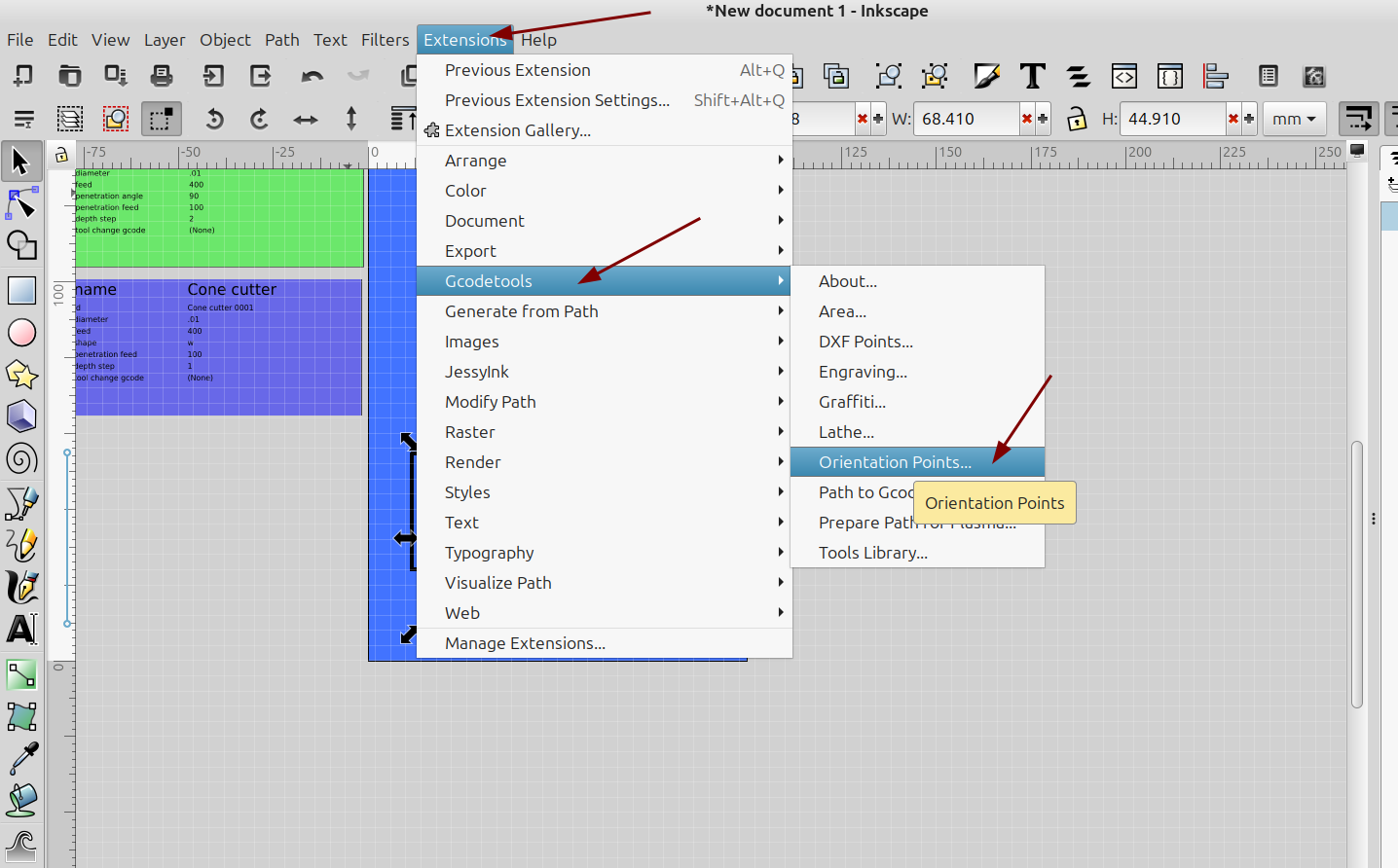
It's pretty easy to do this just open the gcodetools extension, set up the tools for the two layers, then set the orientation points and export the gcode with path to gcode.
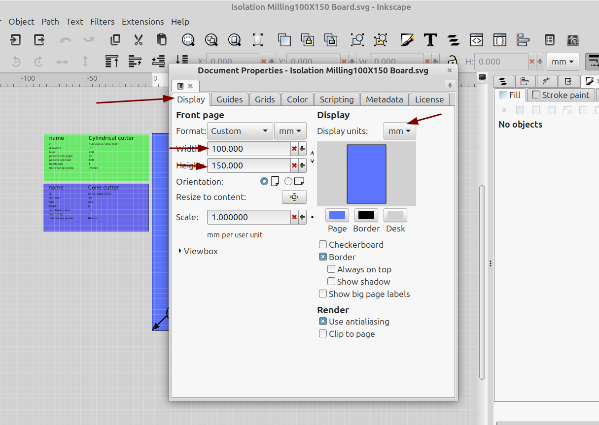
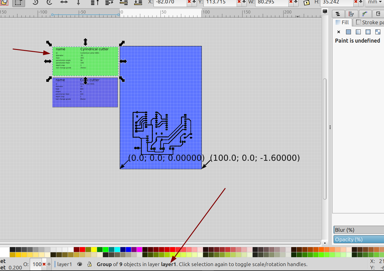
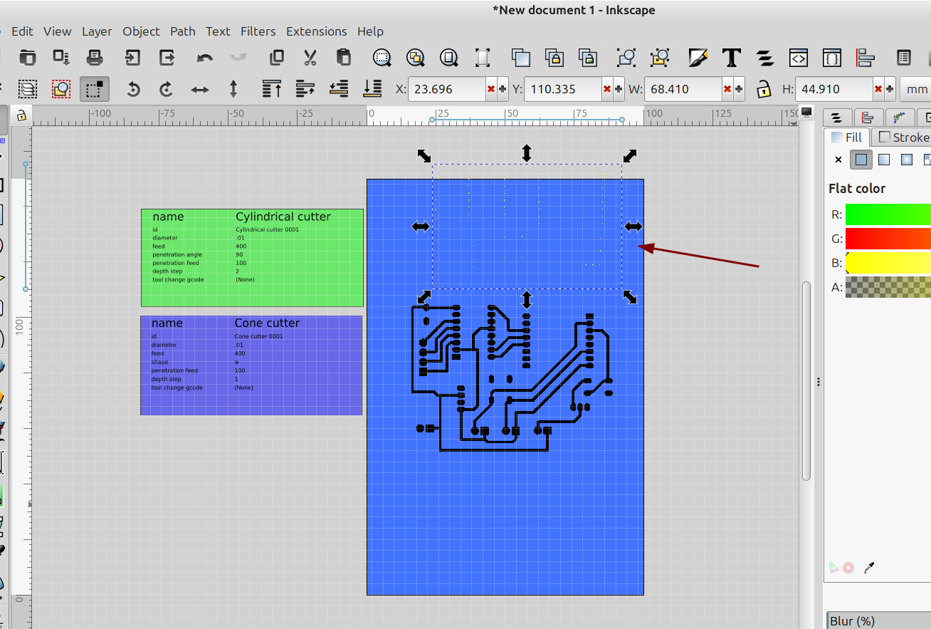
I set the page size in the document properties to the size of the cut area of my cnc so I have an idea of where everything will line up on the bed of the cnc:
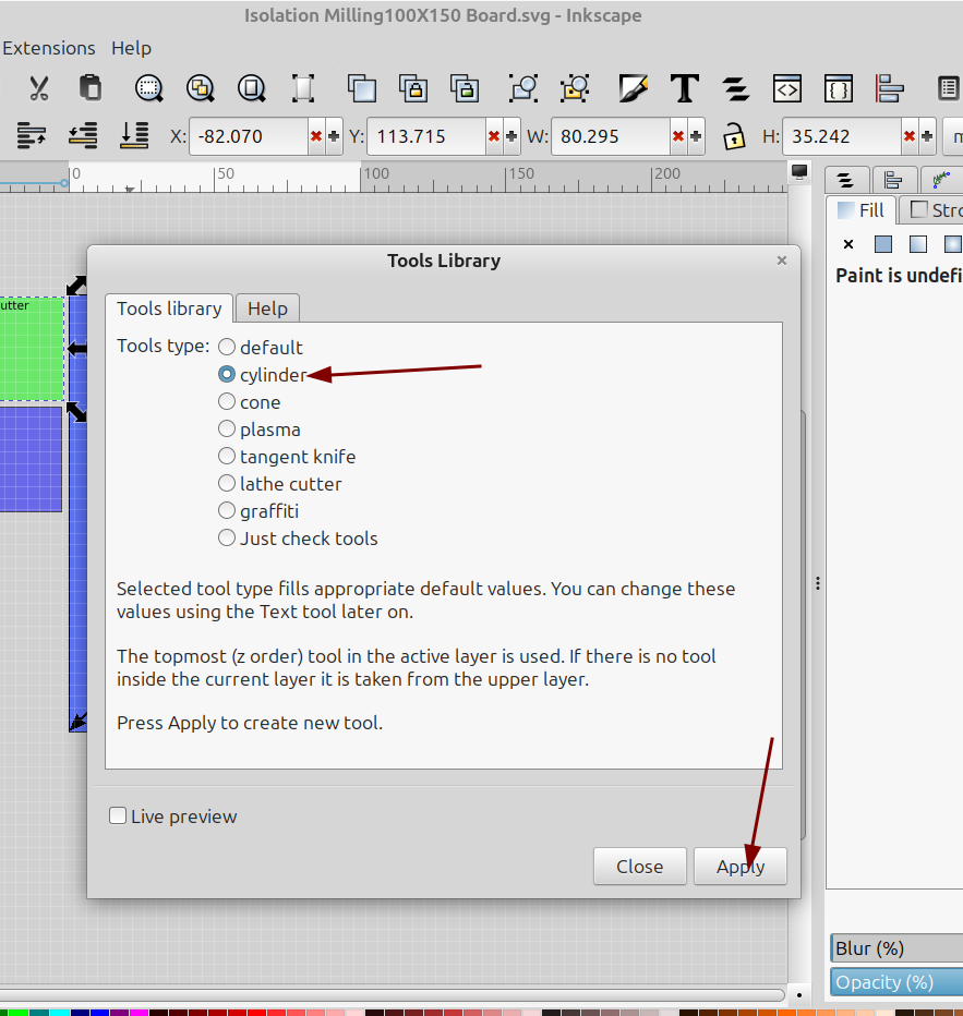
Once you have the tool setup move the box to the layer that the tool will be used for, here I made a cylinder cutter tool and moved it to layer #1 which will be the drill hole layer:
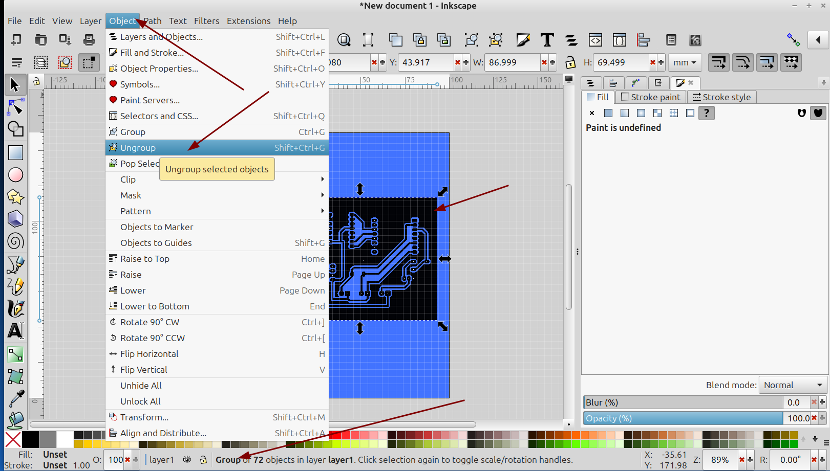
After importing the svg you have to "ungroup" the objects in the svg file. Select the svg and goto Object>Ungroup. You will probably have to do this several times before everything is no longer in a group, there is a notification at the bottom that shows the status:
There is also an extension that will ungroup everything go to Extensions>Arrange>Deep Ungroup
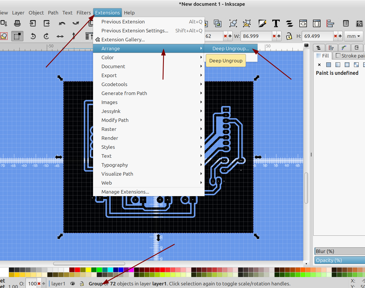
Now you can see that everything is just a path or object and not in a group:
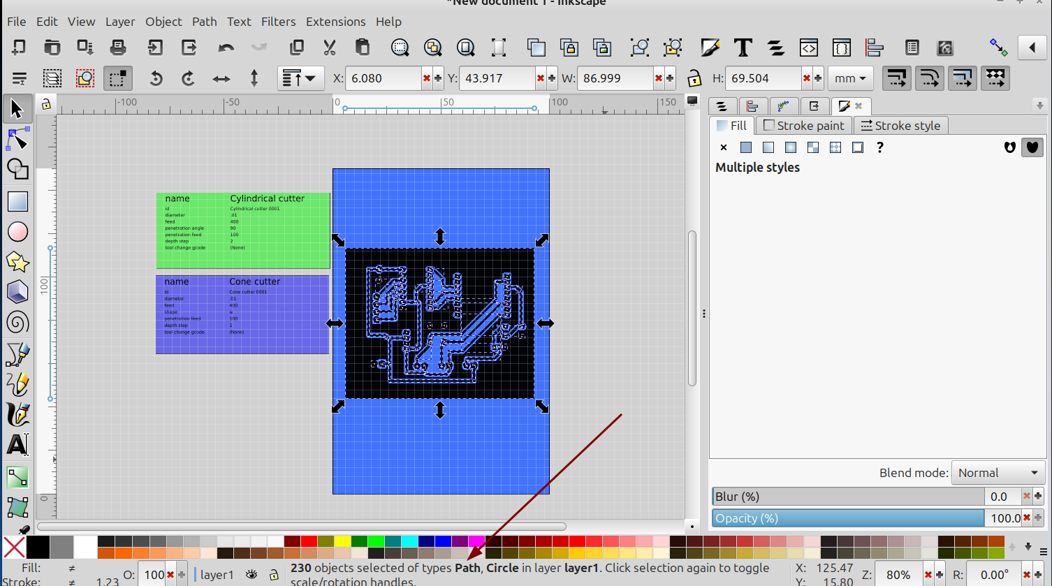
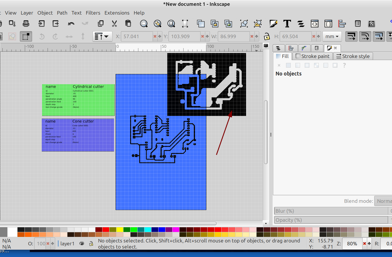
Now that everything is ungrouped you can get rid of the copper pour if there is one, just select it and drag it to the side to make sure all of the important things like the pads, traces and dots for the holes are still there and then press delete:
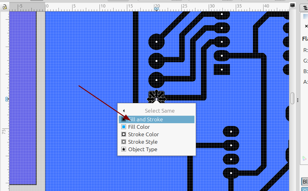
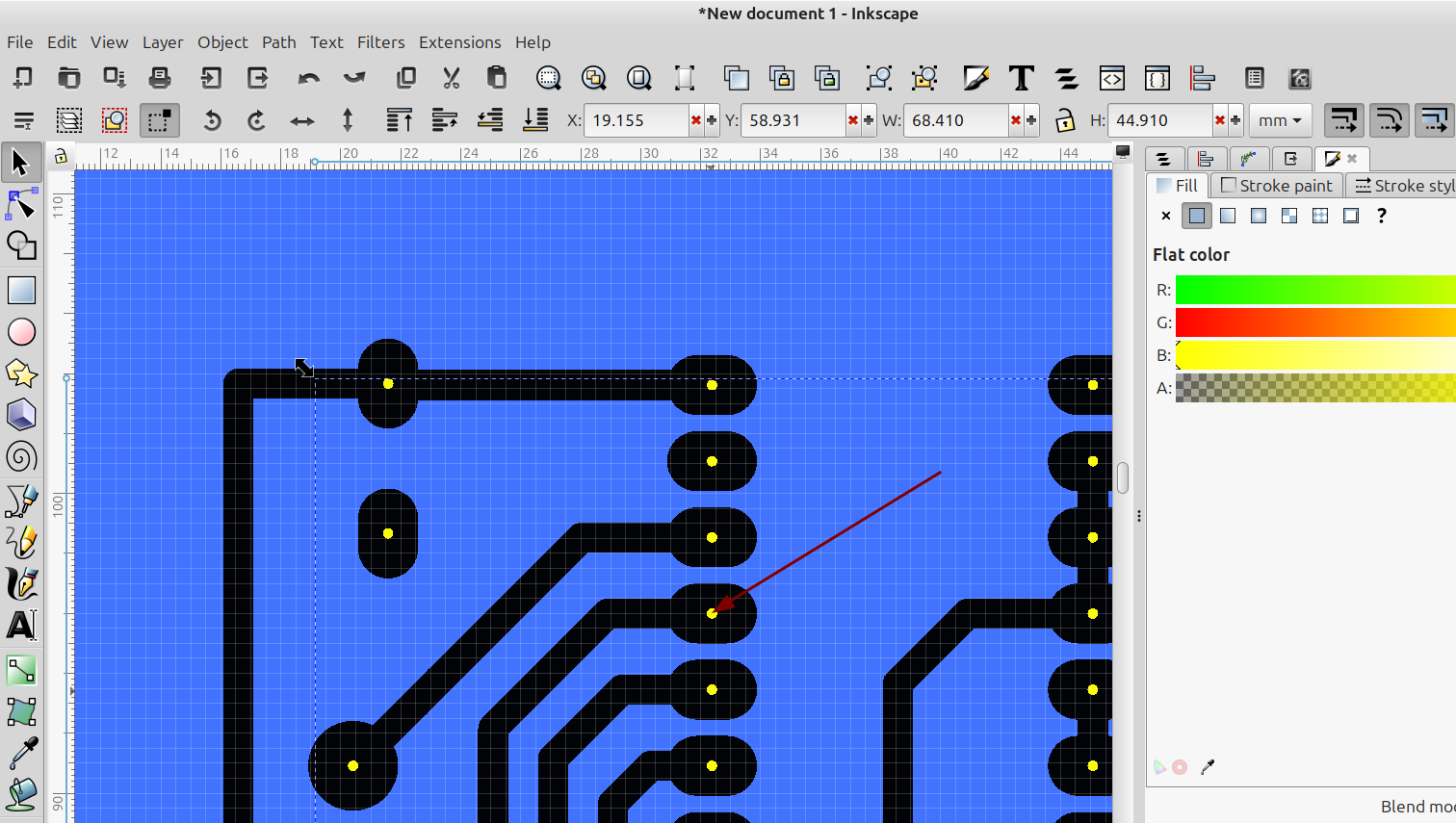
Next select one of the dots for the drill holes, right click on it go to select same and select the objects with the same fill and stroke:
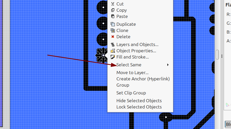
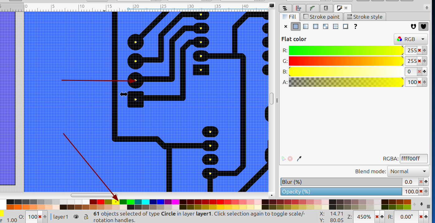
Now all of the drill holes should be selected, I changed the color so they are easier to see:
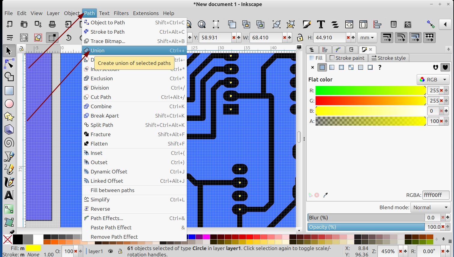
With the drill holes still selected go to Path>Union:
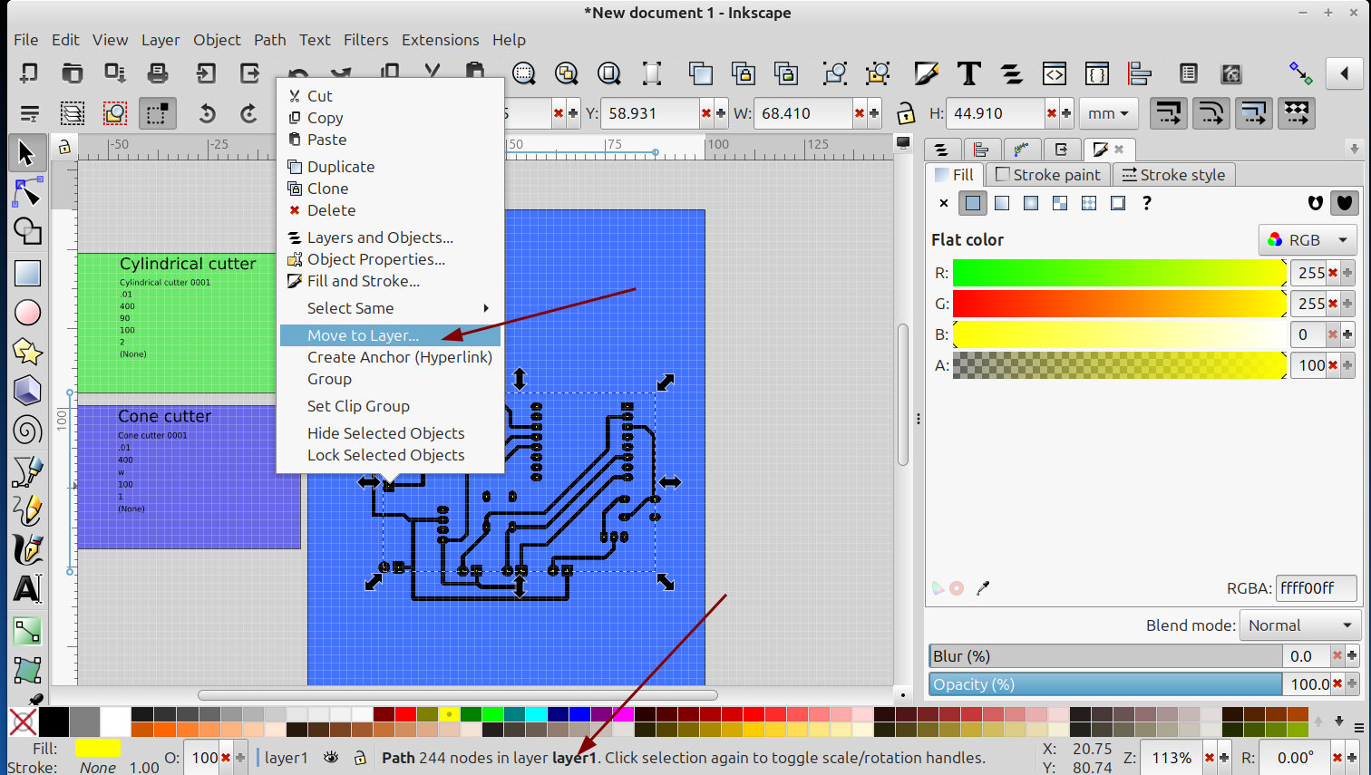
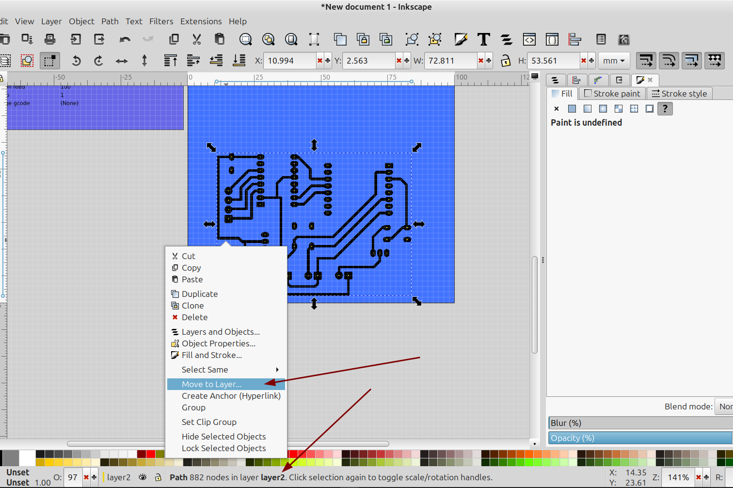
Now all of the drill holes are combined and can be moved to layer 1:
Move the drill marks to the side so you can select the traces, you will probably need to click right on the center of one of the dots to avoid moving the traces, if you do move one just hit undo:
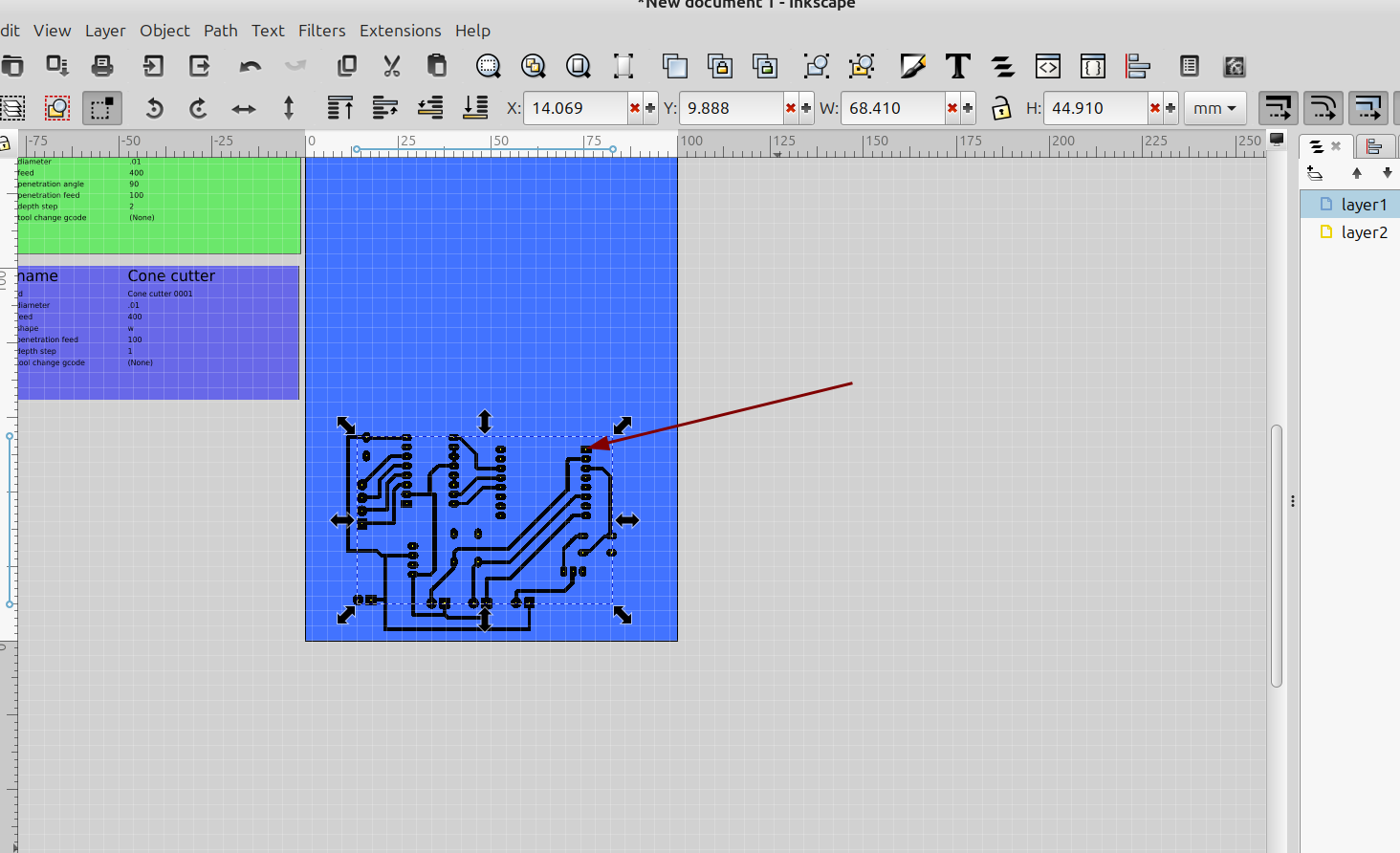
Now select all of the traces and pads and goto Path>Object to path, then Stroke to path and then Union:
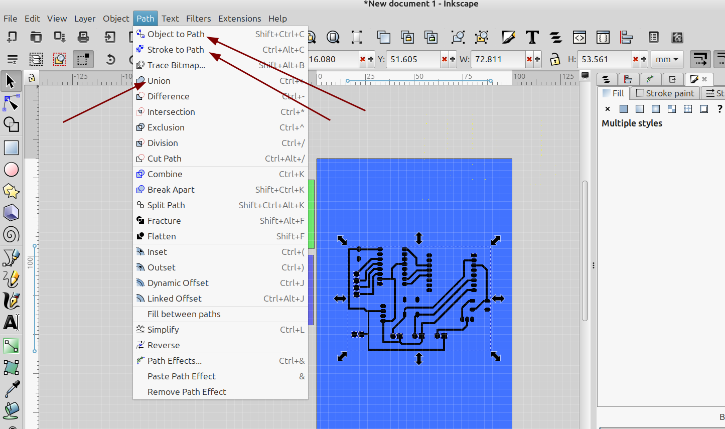
Now the traces should be one object and can be moved to layer 2:
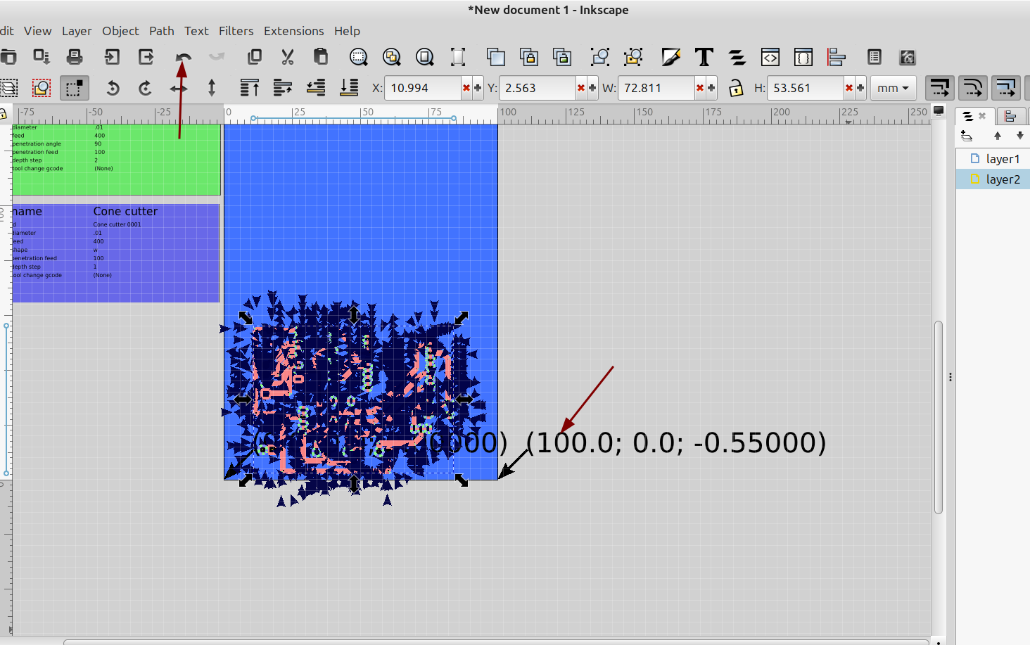
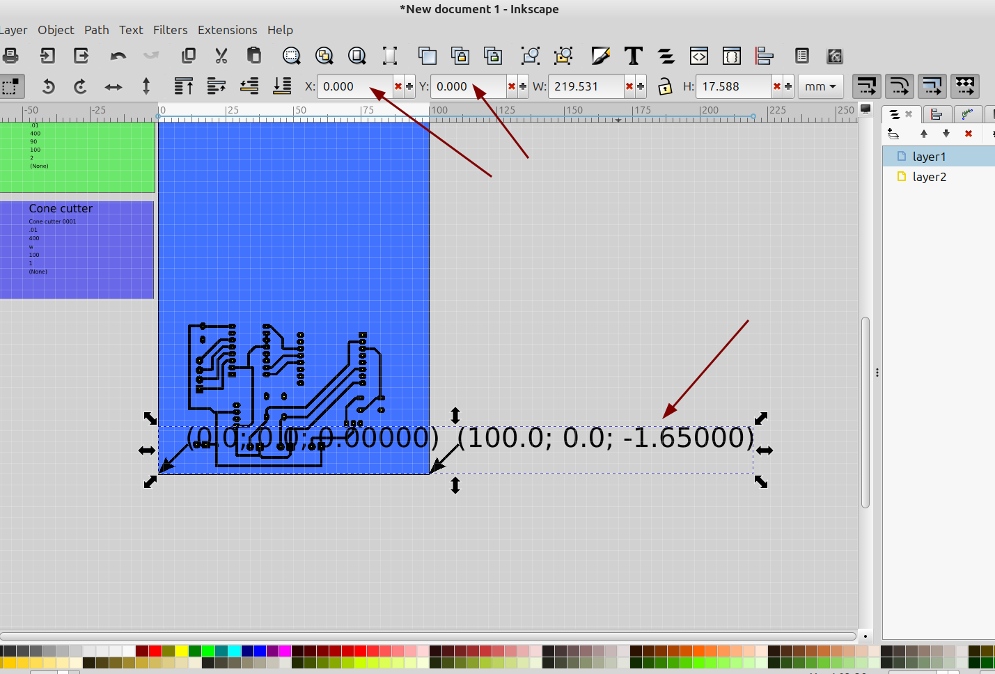
Next move the drill holes back to where they are on top of the traces and are lined up with the center of the pads, then select everything and move it to the lower left hand corner of the page. It doesn't really matter where you position the svg in your cut area as long as the "orientation text" zero point (0,0) is where you want your origin to be.
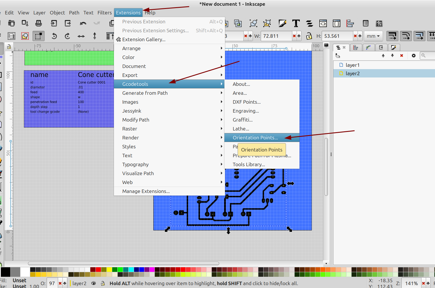
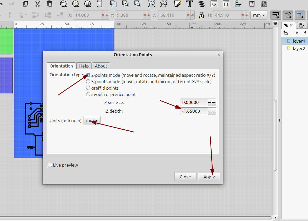
Next select just the traces and open up the gcode tools extension and set the orientation points:
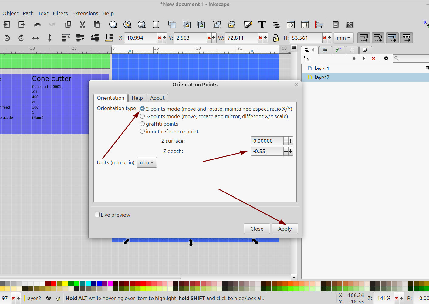
Set the z depth to the desired depth of your cutter and the units to whatever you are using, I used mm and -.55 for my cutter depth which is just enough to get through the copper layer:
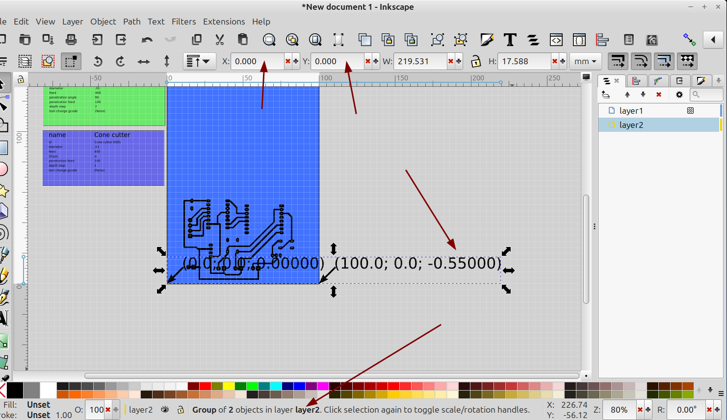
Once the orientation points are generated select the text and make sure the x and y are at zero and they are are on the correct layer for the traces:
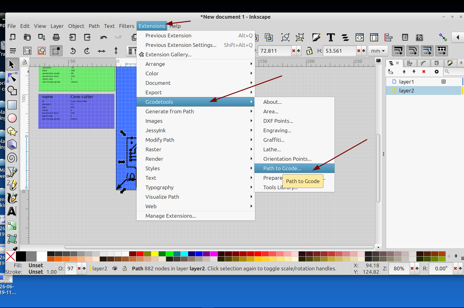
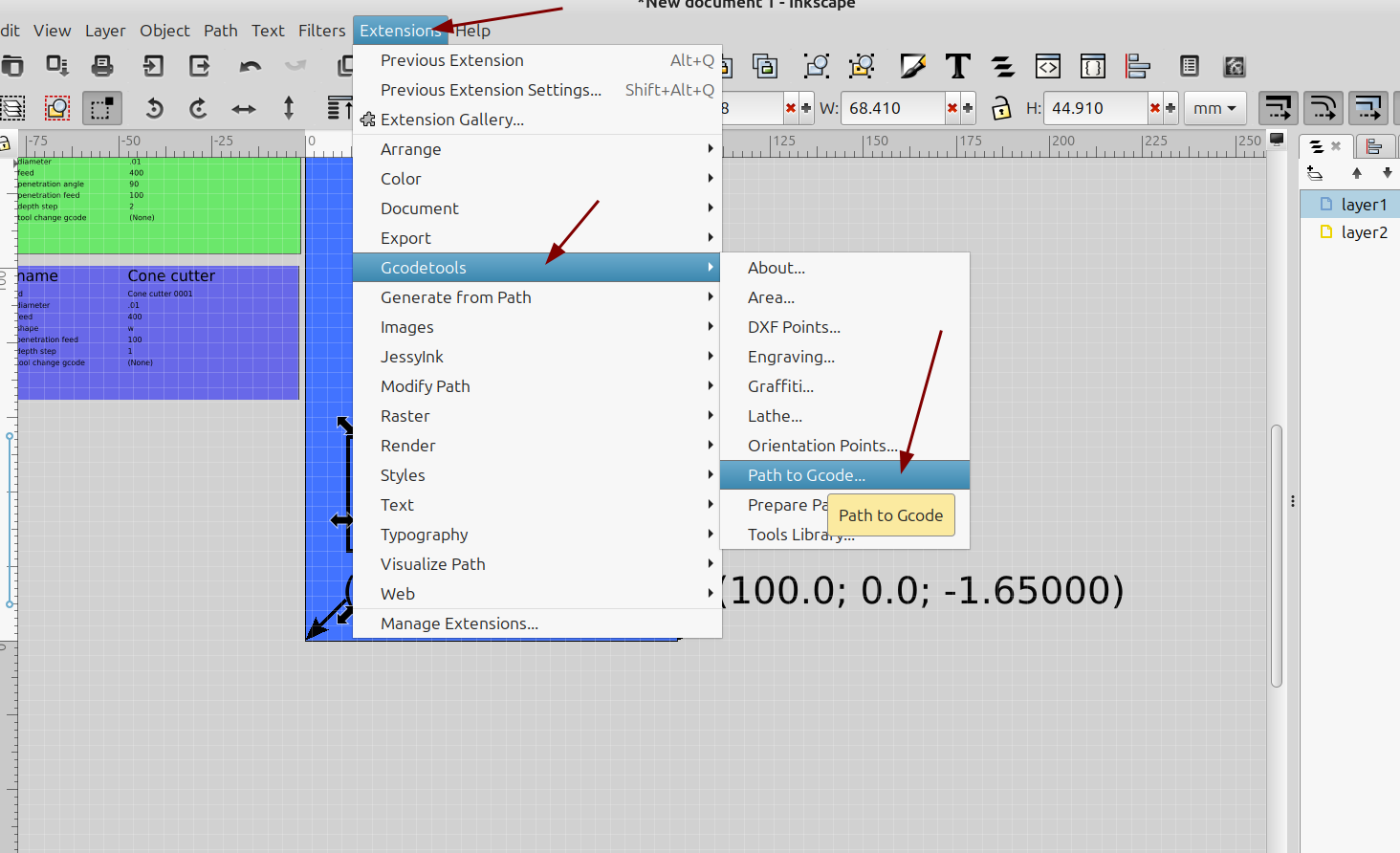
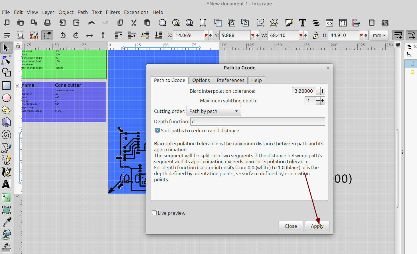
With just the traces selected again goto Extensions>Gcodetools>Path to gcode:
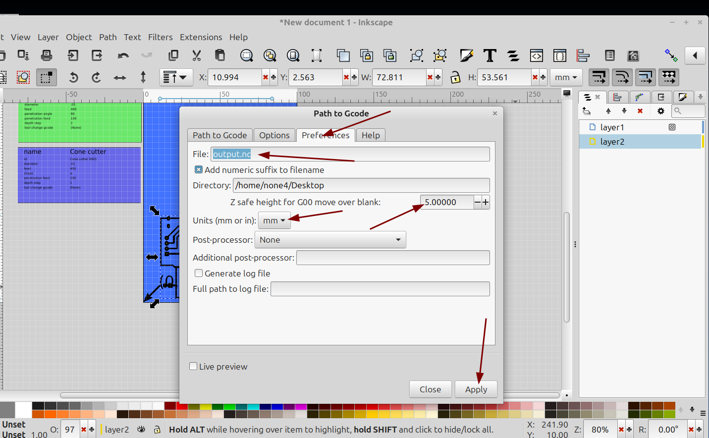
On the preferences tab set the file output directory, z height safe distance and units:
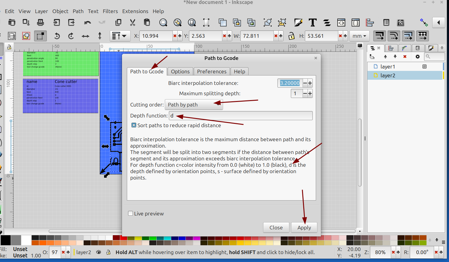
Then on the path to gcode tab set the cutting order, depth function should be "d" for orientation points and click apply:
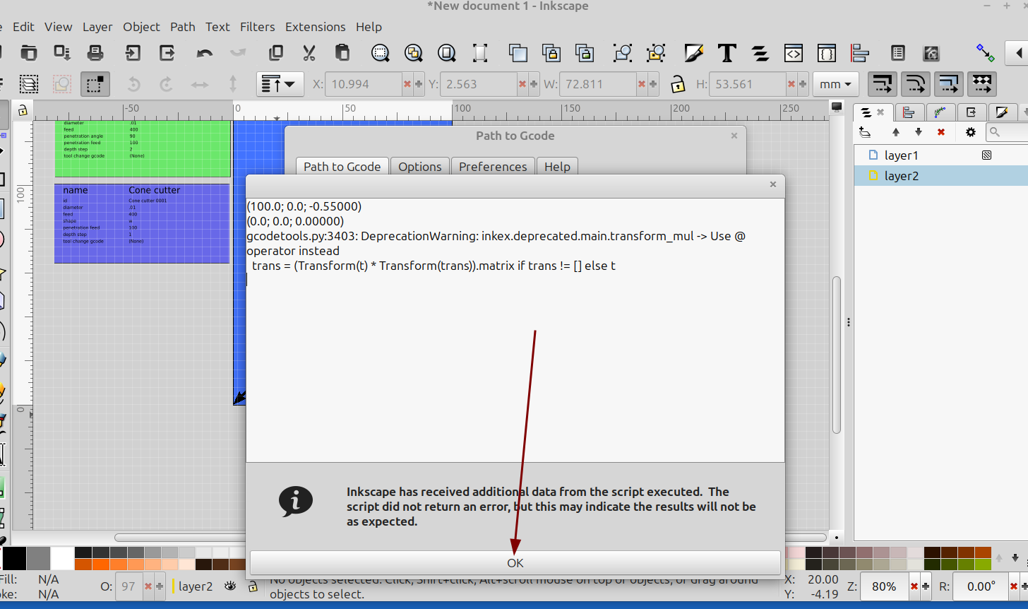
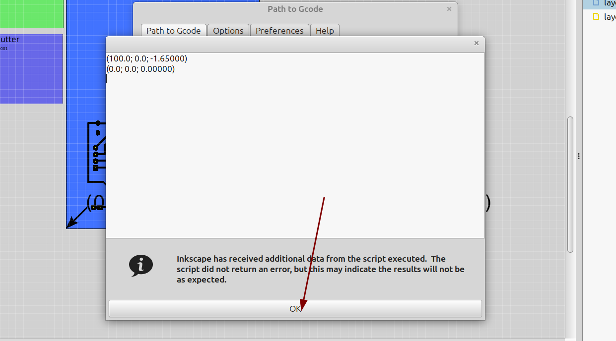
It will probably generate a warning, just click ok:
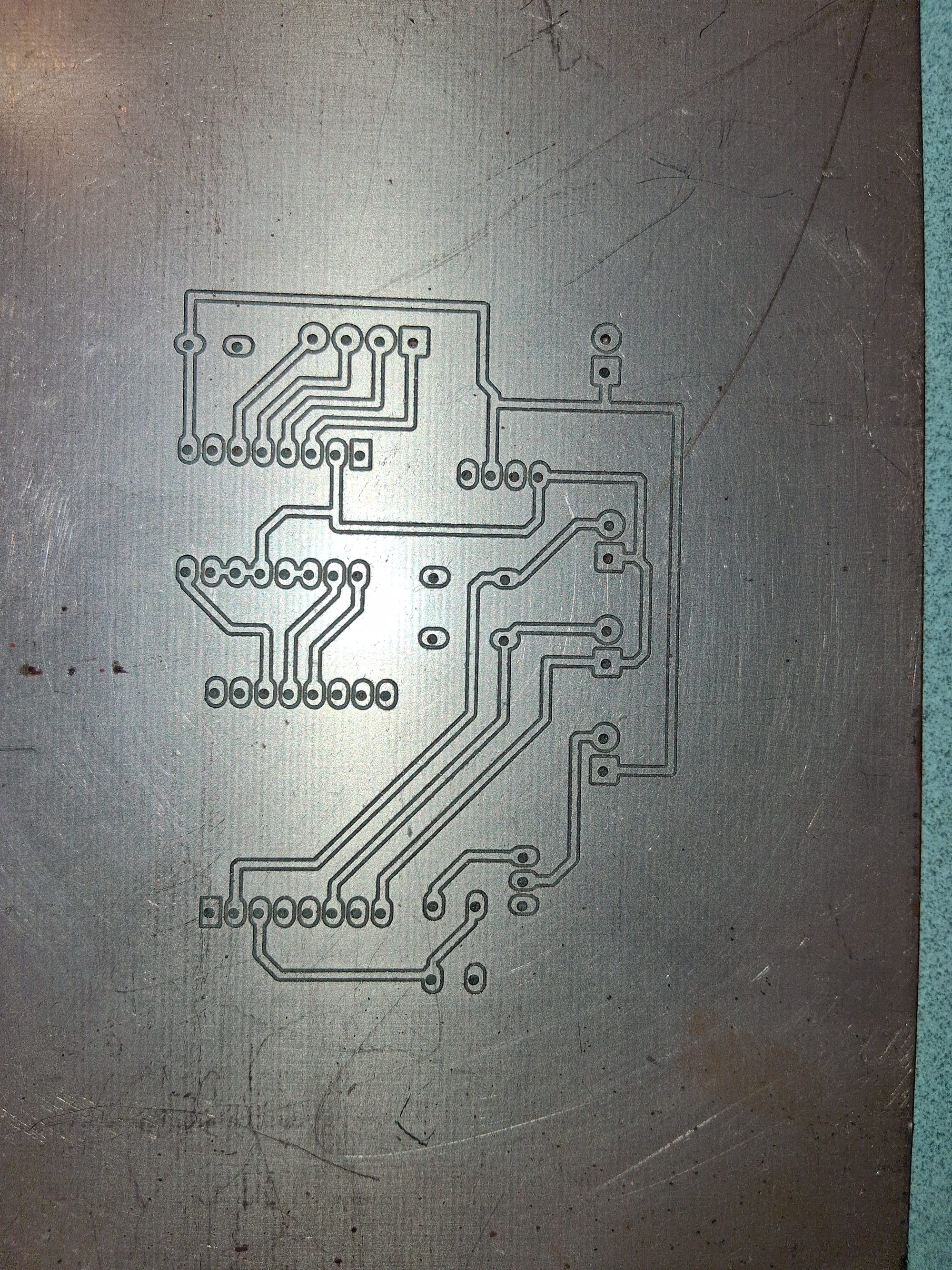
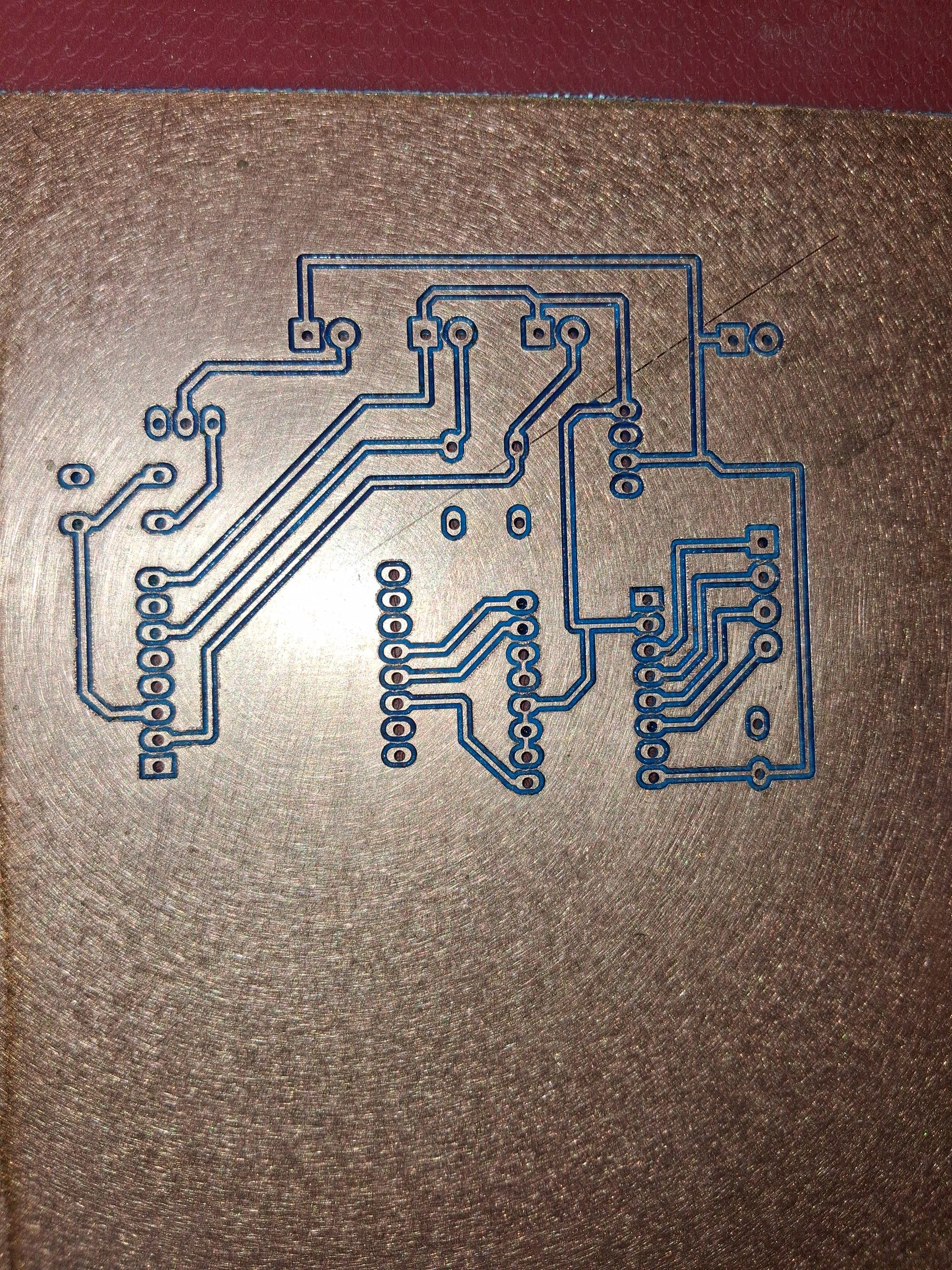
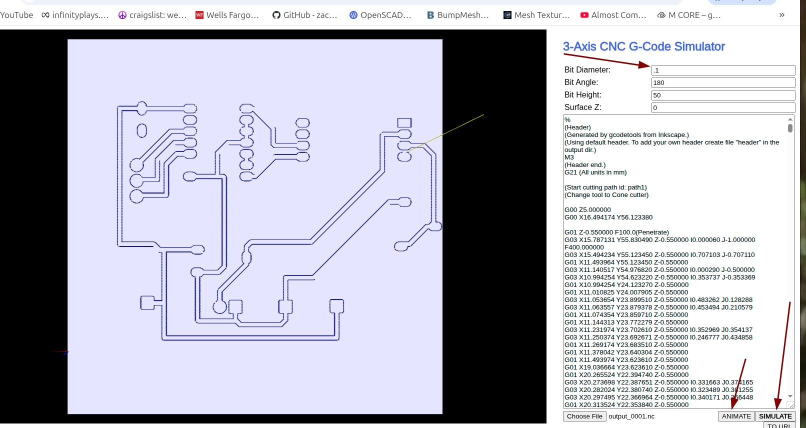
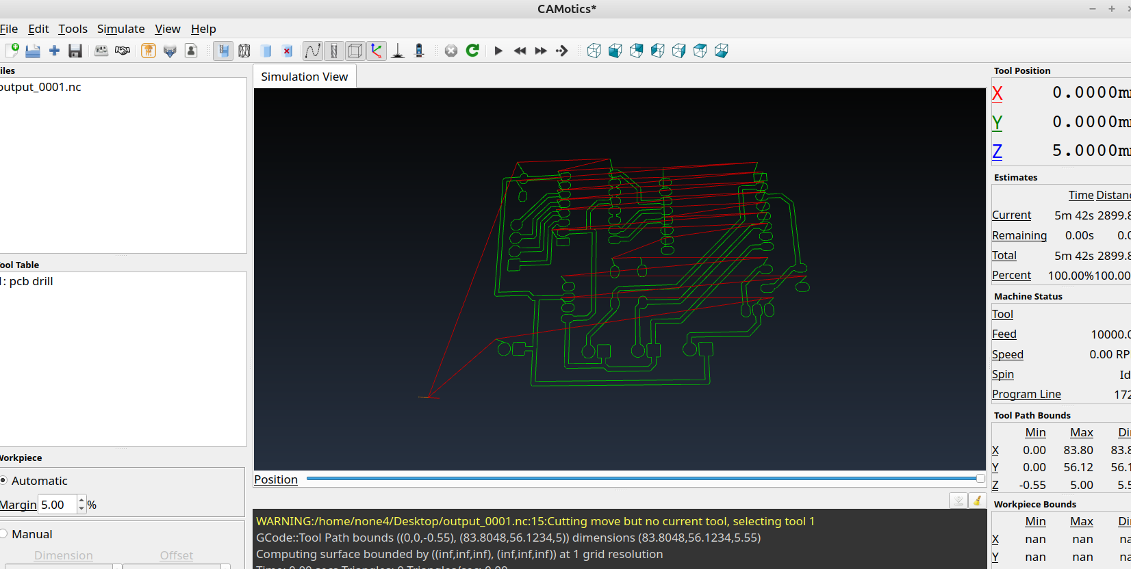
Now there should be a gcode file saved to the location you told it to save to, you can open the file with a gcode viewer and see how it looks.
There are a several good open source options for simulating gcode like:
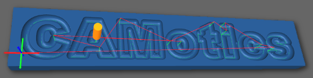
or Camotics:
Next do the same for the drill holes:
Click undo and delete the orientation point text for the traces and generate new points for the drill holes:
Select just the drill holes:
Generate new orientation points for them. Make sure the orientation points for the drill holes and the traces are exactly the same so they line up properly when you go to mill them out :

Set the z depth for the through holes:
And then again path to gcode:
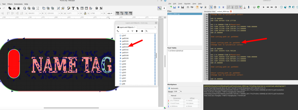
Now both files can be opened with camotics, to show both go to simulate then run:
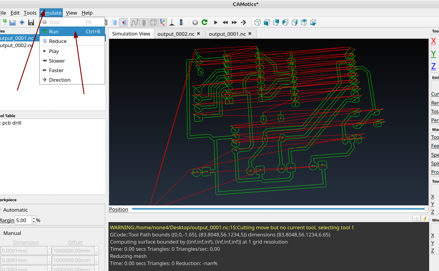
And now you can see both the traces and drill holes are set up and ready to mill, you can also take a look at the gcode files and check the drill depth and add a header or footer to move the cnc to the desired position when it's done.
It may seem like this is a long process but once you have it down it only takes about 5 minutes to generate a gcode file from an svg and the results are really good, plus once you save the svg file you will have most of the steps done already when you do a different board.