
3D part design with OpenSCAD #153: A resistor generator for Kicad.
In my last post I had mentioned I was going to make a resistor customizer since the default 3d resistor models in Kicad were kind of plain.
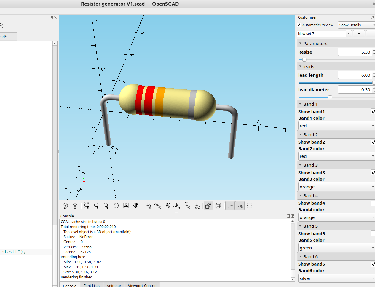
It was pretty easy to make one in a few minutes that produces some good results and allows me to change the color bands to show the resistor value and adjust the size, I will probably add a color code calculator at a future date but for now this achieves what I wanted it to do.
here is the code:
//
// 6/30/2026 Resistor Calculator and 3D model generator Version 1 By Infinityplays.com
// License- Public Domain
Resize=5.30;//[2.65:2.65:53]
/*[leads]*/
lead_length=6;//[2:.01:6]
lead_diameter=.30;//[.1:.01:.6]
/*[Hidden]*/
$fn=$preview?60:150;;
/*[Band 1]*/
Show_band1=true;
Band1_color="brown";//[brown,black,red,orange,yellow,green,blue,violet,grey,white,gold,silver]
/*[Band 2]*/
Show_band2=true;
Band2_color="black";//[brown,black,red,orange,yellow,green,blue,violet,grey,white,gold,silver]
/*[Band 3]*/
Show_band3=true;
Band3_color="red";//[brown,black,red,orange,yellow,green,blue,violet,grey,white,gold,silver]
/*[Band 4]*/
Show_band4=true;
Band4_color="orange";//[brown,black,red,orange,yellow,green,blue,violet,grey,white,gold,silver]
/*[Band 5]*/
Show_band5=true;
Band5_color="yellow";//[brown,black,red,orange,yellow,green,blue,violet,grey,white,gold,silver]
/*[Band 6]*/
Show_band6=true;
Band6_color="silver";//[brown,black,red,orange,yellow,green,blue,violet,grey,white,gold,silver]
module main_body(){
color("khaki"){
minkowski(){
translate([1.2,0,0])
rotate([0,90,0])
cylinder(7.1,.01,.01);
sphere(1.5);
}
translate([1.2,0,0])
sphere(1.6);
translate([8.2,0,0])
sphere(1.6);
}}
module lead(){
color("lightgrey"){
rotate_extrude(90)
translate([1, 0, 0])
circle(r =lead_diameter);
rotate([90,0,0])
translate([1,0,0])
cylinder(lead_length,lead_diameter,lead_diameter);
rotate([0,90,0])
translate([0,1,-6])
cylinder(6,lead_diameter,lead_diameter);
}}
module leads(){
rotate([90,0,0]){
translate([10.8,-1,0])
lead();
mirror([1,0,0])
translate([1.2,-1,0])
lead();
}}
module band1(){
if(Show_band1)
color(Band1_color)
translate([1.5,0,0])
rotate([0,90,0])
linear_extrude(.8)
circle(1.52);
}
module band2(){
if(Show_band2)
color(Band2_color)
translate([2.6,0,0])
rotate([0,90,0])
linear_extrude(.8)
circle(1.52);
}
module band3(){
if(Show_band3)
color(Band3_color)
translate([3.7,0,0])
rotate([0,90,0])
linear_extrude(.8)
circle(1.52);
}
module band4(){
if(Show_band4)
color(Band4_color)
translate([4.8,0,0])
rotate([0,90,0])
linear_extrude(.8)
circle(1.52);
}
module band5(){
if(Show_band5)
color(Band5_color)
color("green")
translate([5.9,0,0])
rotate([0,90,0])
linear_extrude(.8)
circle(1.52);
}
module band6(){
if(Show_band6)
color(Band6_color)
color("green")
translate([7.1,0,0])
rotate([0,90,0])
linear_extrude(.8)
circle(1.52);
}
resize([Resize,0,0], auto=true){
translate([2.2,0,2]){
main_body();
leads();
band1();
band2();
band3();
band4();
band5();
band6();
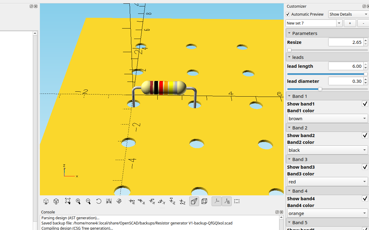
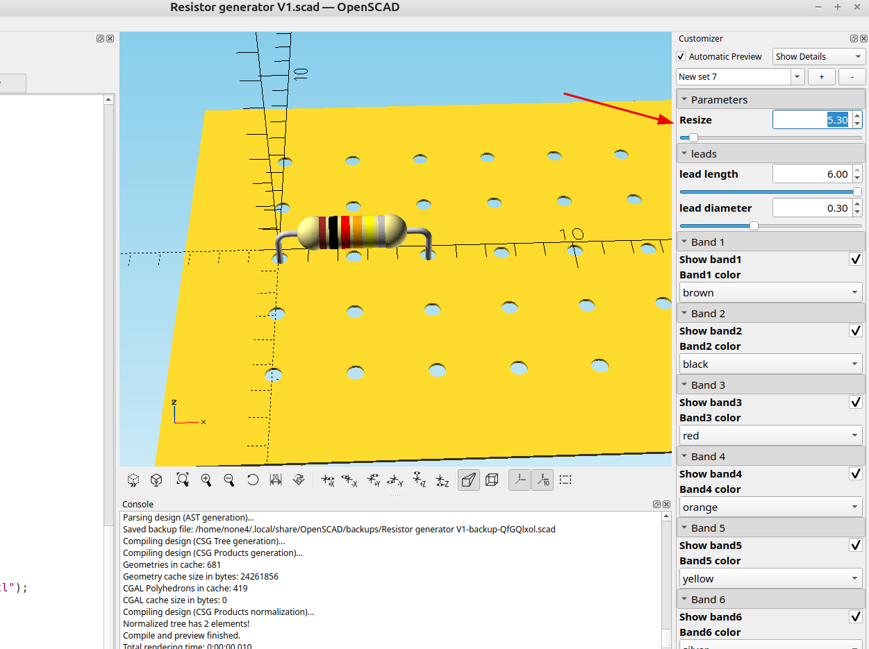
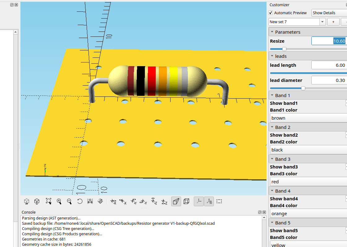
}}I adjusted the resize scaling a bit so the leads will line up with 2.54 mm holes
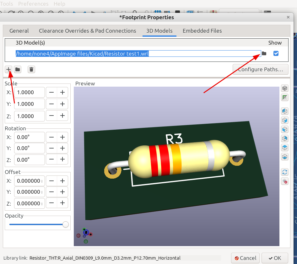
I covered how to import 3d models into Kicad in the last post and it's pretty easy, just export the component as a .WRL file and then save it to a folder that's easy to find, then in Kicad double click on the outline of the component in the PCB board editor and import the file:
And here it is next to the plain resistors:
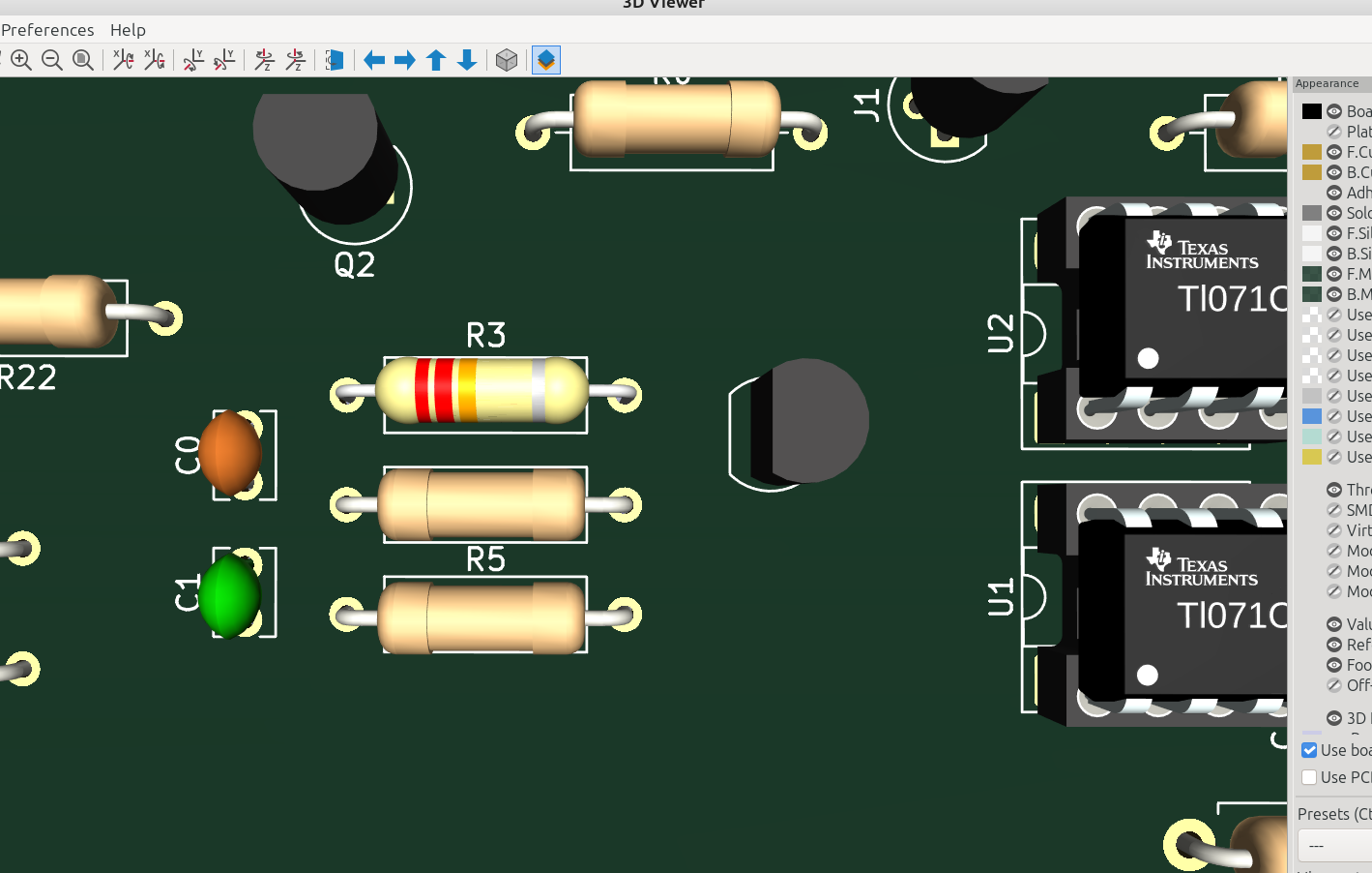
Now I can save different values to a resistor folder and I will have a nice selection of color coded resistors for my board models.