
3D part design with OpenSCAD # 152: How to make your own 3d models for Kicad from scratch.
Quite often when I am designing a circuit and I want to make a 3d rendering of it there are models missing and if you look online most places with free models want you to sign up or the models are pretty basic, there are a lot of free models online if you can find them but if you are like me it's more fun to make your own.
Recently I needed a model of an OP amp so I used OpenSCAD to make a customizer that I can add text and a logo to the IC, adjust the number of pins, etc. As with all of the stuff I make it's a work in progress and I will be adding features and fixing some errors over time.
I am using the latest version of Kicad:
And the latest development snapshot of OpenSCAD:

Here is the code:
//

//Dual Inline Package IC customizer Version 3 for Kicad  by InfinityPlays.com//
//License- Public Domain

/*[Scale for Output to Kicad]*/
Scale_all=1;//[.001:.001:1]

/*[Main Body]*/
Number_of_pins=8;//[4:2:28]
Pin_length=3;//[1:.01:5]
show_notch=false;
Notch_adjust=.1;//[-4:.01:4]

/*[Text]*/
Input_text="U1";
Font_name="";
text_size=2;//[.1:.1:3]
Move_text_X=0;//[-12:.01:12]
Move_text_Y=0;//[-2:.01:2]
Text_rotate=90;//[-180:.01:180]

/*[SVG Logo]*/
Show_logo=false;
Path_to_SVG_file="";
Scale_logo=1;//[.001:.001:1]
Move_logoX=0;//[-10:.01:10]
Move_logoY=0;//[-10:.01:10]
Move_logoZ=1;//[-10:.01:10]

module body(){
 translate([0,-.25,0])
minkowski(){
 linear_extrude(1.3,scale=.90)
 square([2,Number_of_pins/2.5],center=true);
 mirror([0,0,1])
 linear_extrude(1.3,scale=.92)
 square([3.8,Number_of_pins/1.2],center=true);
 sphere(.2,$fn=60);
}

}

module pins(){
 $fn=100;
 color("azure")
 translate([0,1.5,0])
for(i=[-Number_of_pins/4:1:Number_of_pins/4-1])
  translate([0,i*2.54,0])
  rotate([90,0,0]){
  rotate([0,0,90])
  translate([-1.5,-3.81,-.1])
  cube([1.1,.25,1.1]);
  rotate([0,0,90])
  translate([-Pin_length-.5,-3.78,.15])
  cube([Pin_length,.2,.5]);
  translate([3.36,-.4,-.1])
  rotate_extrude(angle = 90)
  translate([.2,0,0])
  square([.25,1.1]);
  translate([3.36,0.05,-.1])
  rotate([0, 0, 180])
  cube([2,.25,1.1]);
}
}

module Text(){
  color("white")
  linear_extrude(1.6)
  rotate([0,0,Text_rotate])
  translate([Move_text_X,Move_text_Y,1.3])
  text(Input_text,font=Font_name,spacing=1,
  size=text_size,valign="center",halign="center",$fn=50);
}

 module Logo(){
  if(Show_logo)
  color("white")
  rotate([0,0,90])
  translate([Move_logoX,Move_logoY,Move_logoZ])
  linear_extrude(.65)
  scale([Scale_logo,Scale_logo,.1])
  import(Path_to_SVG_file);
}

 translate([0,0,0]){
 scale([Scale_all,Scale_all,Scale_all]){
 difference(){
 color("#242020")
 body();
if(show_notch){
 translate([0,Number_of_pins/2+Notch_adjust,1])
 #color("#242020")
 cylinder(.5,1,1,$fn=30);
 translate([-2.1,Number_of_pins/2+Notch_adjust-1,1])
 #color("#242020")
 cylinder(.5,.4,.3,$fn=30);
}}
 mirror([1,0,0])
 pins();
 pins();
 Text();
 Logo();
}}
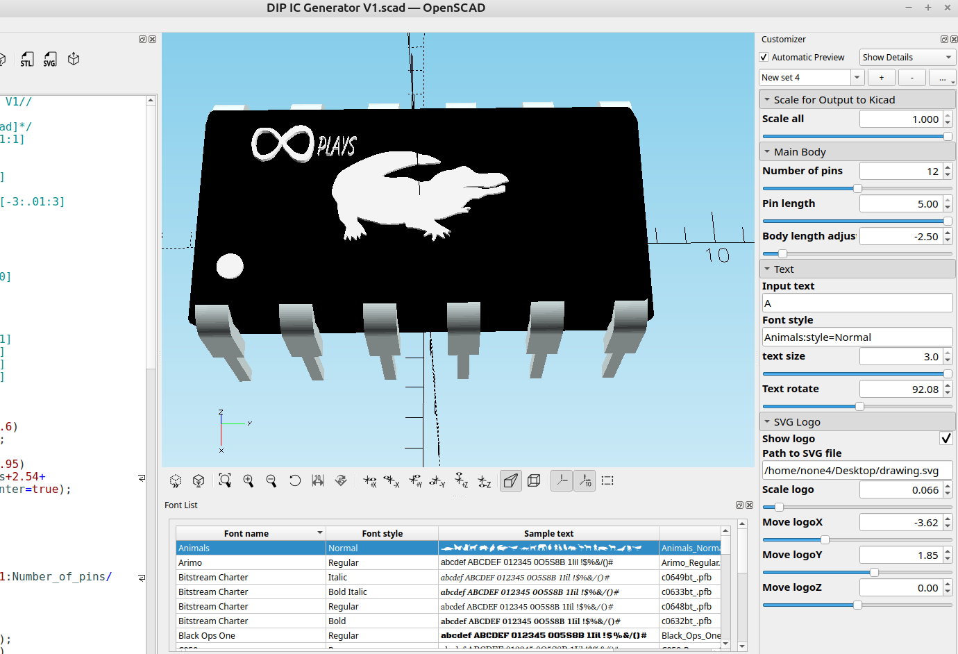
I added the option to load an svg so it can have an image or custom logo:
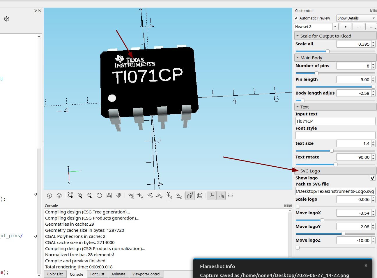
The logo I used for this example came from here:
I am using the Texas Instruments logo for informational and education purposes only, and as a long time user of their products I can confidently say they are an excellent company that provides high quality components at extremely affordable prices for hobbyists. Plus I think their logo looks cool on my finished 3d model.
Here is an ATMEGA 328:
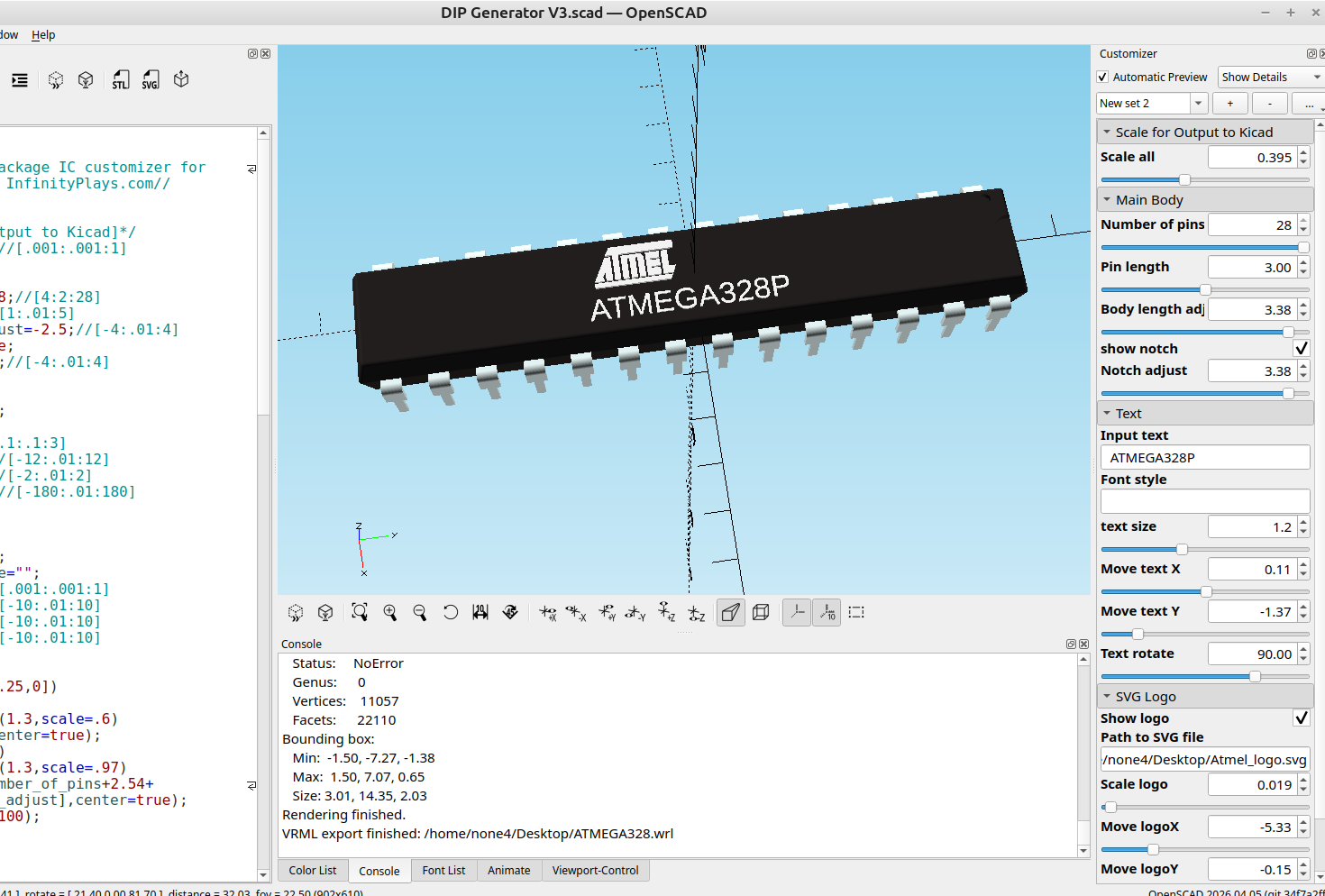
I got the ATMEL logo from here:
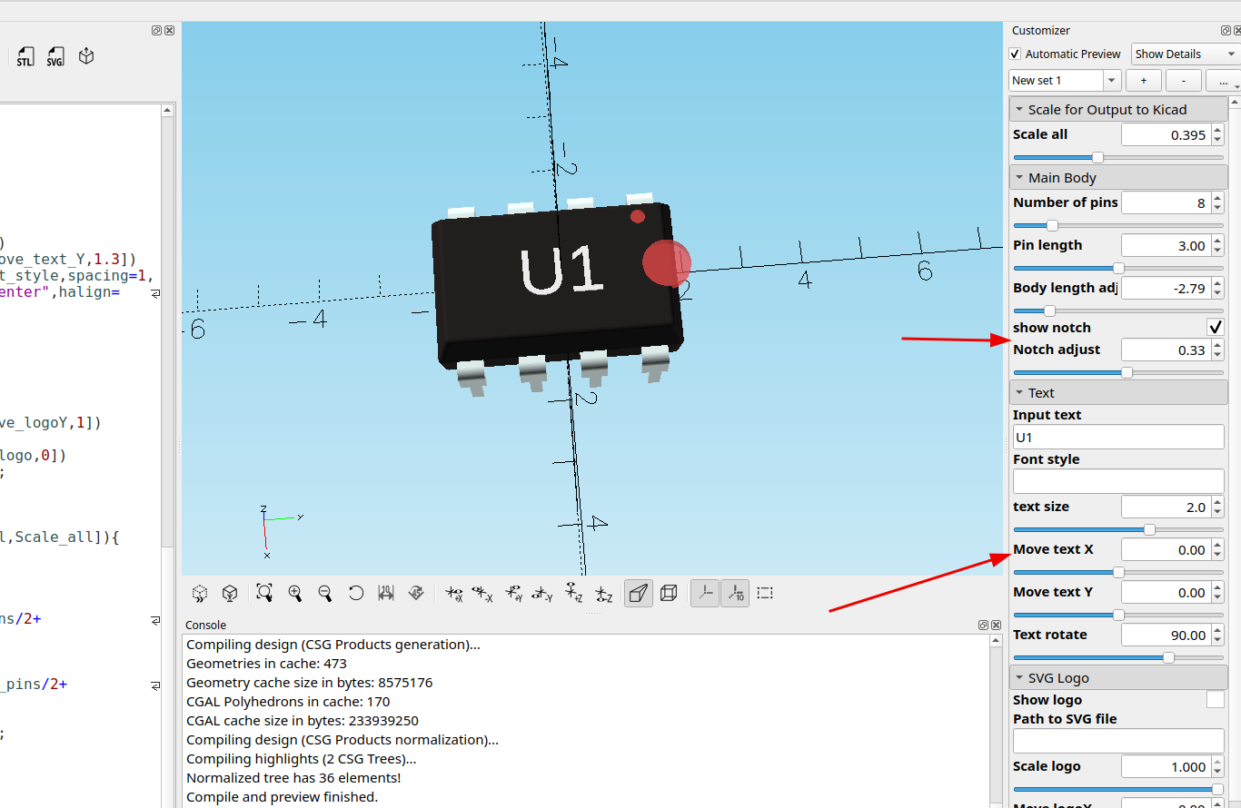
I also updated the code and added a notch:
I also added some adjusters to the text input area since I forgot them before.
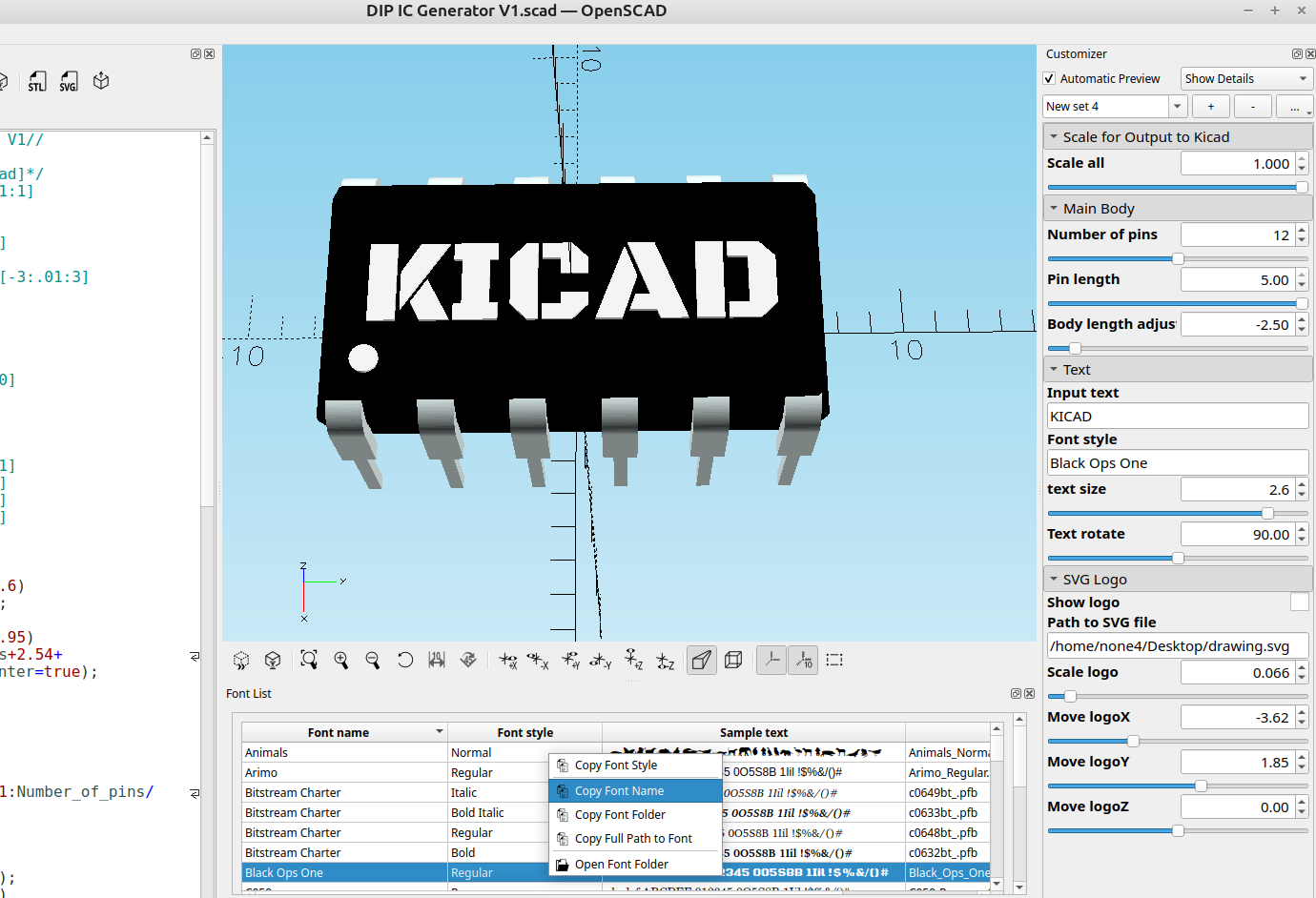
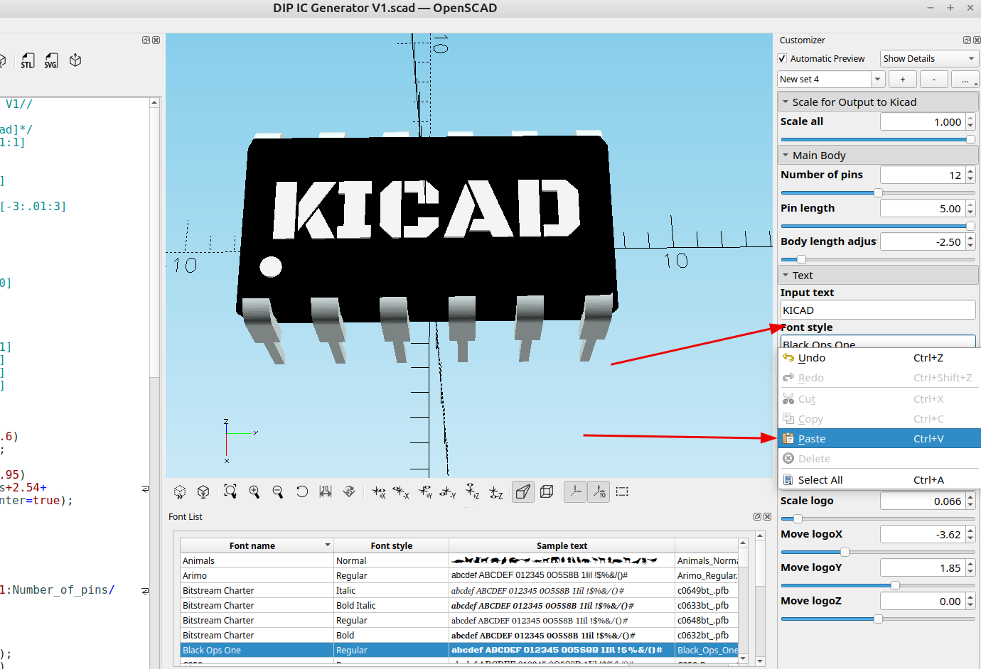
To change the font just open the font selector window, copy the font name and paste it in the font style box:
It's pretty easy to add custom svg files:
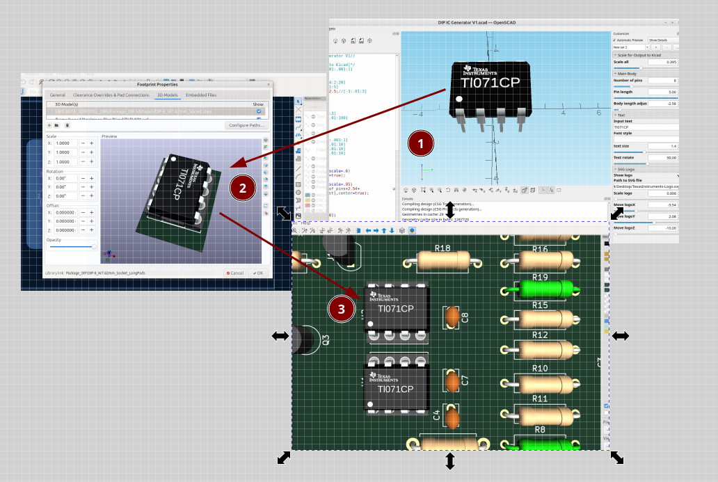
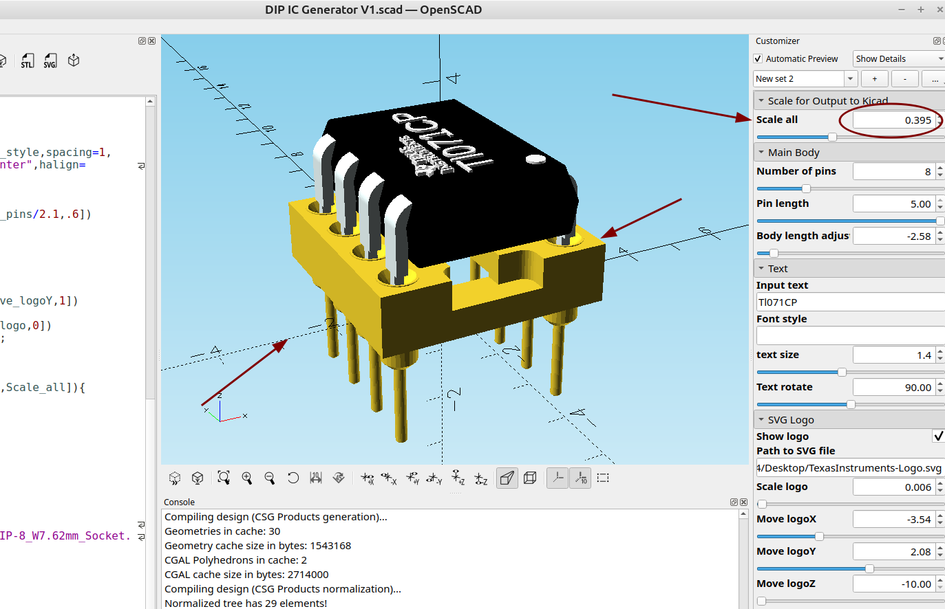
There is also a scale option for Kicad, I'm sure there's a reason the scaling is set so small and maybe I'm missing something (it's probably to save space and so they load faster) but it was pretty easy to fix with OpenSCAD, here is a socket model from the standard Kicad library and I have adjusted the scale of my model to fit it:
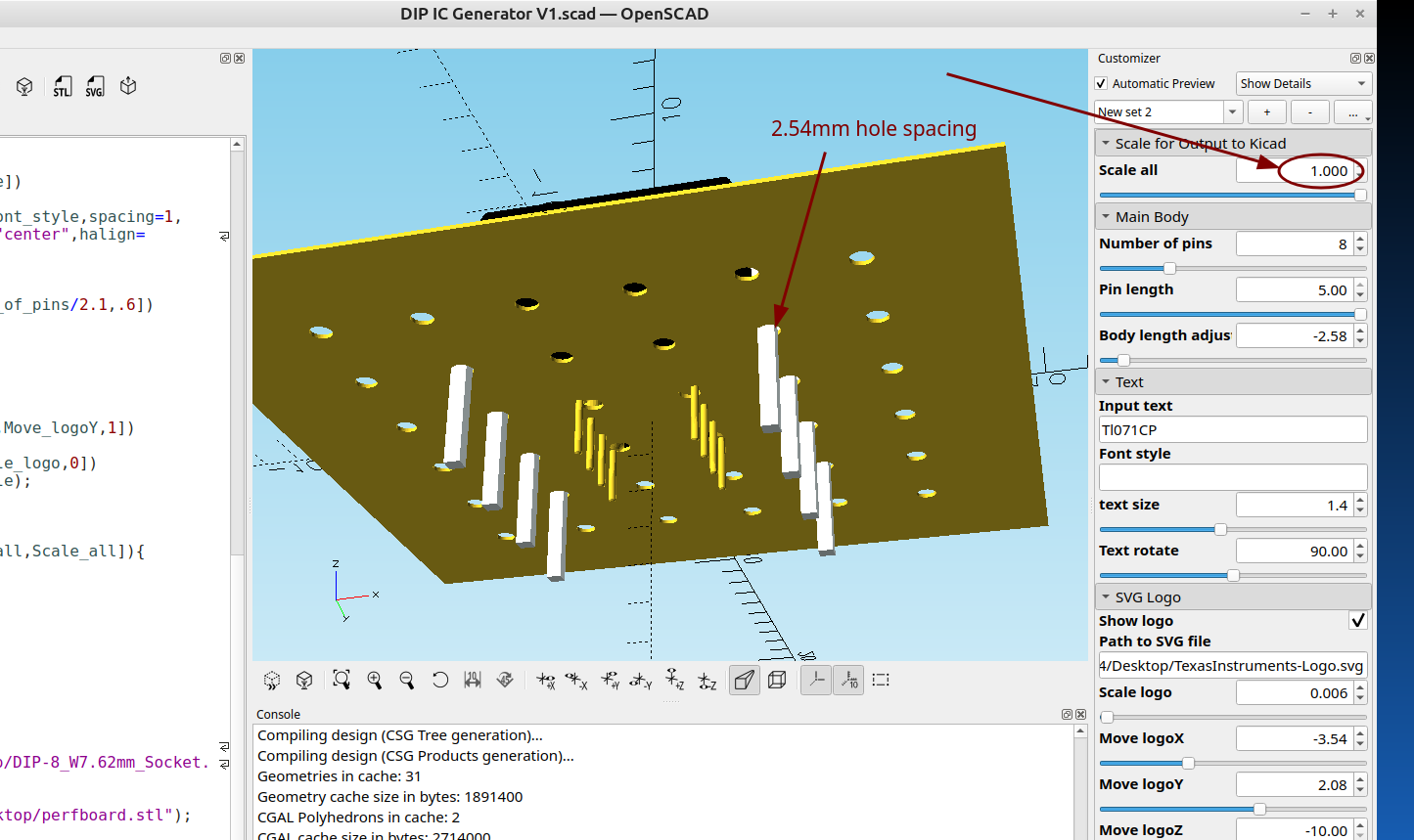
Here it is at normal size on a perfboard with 2.54mm hole spacing, you can see the yellow legs of the model from Kicad, there is an option in Kicad to move and scale the model so this isn't necessary but it was easy to add so added it anyway
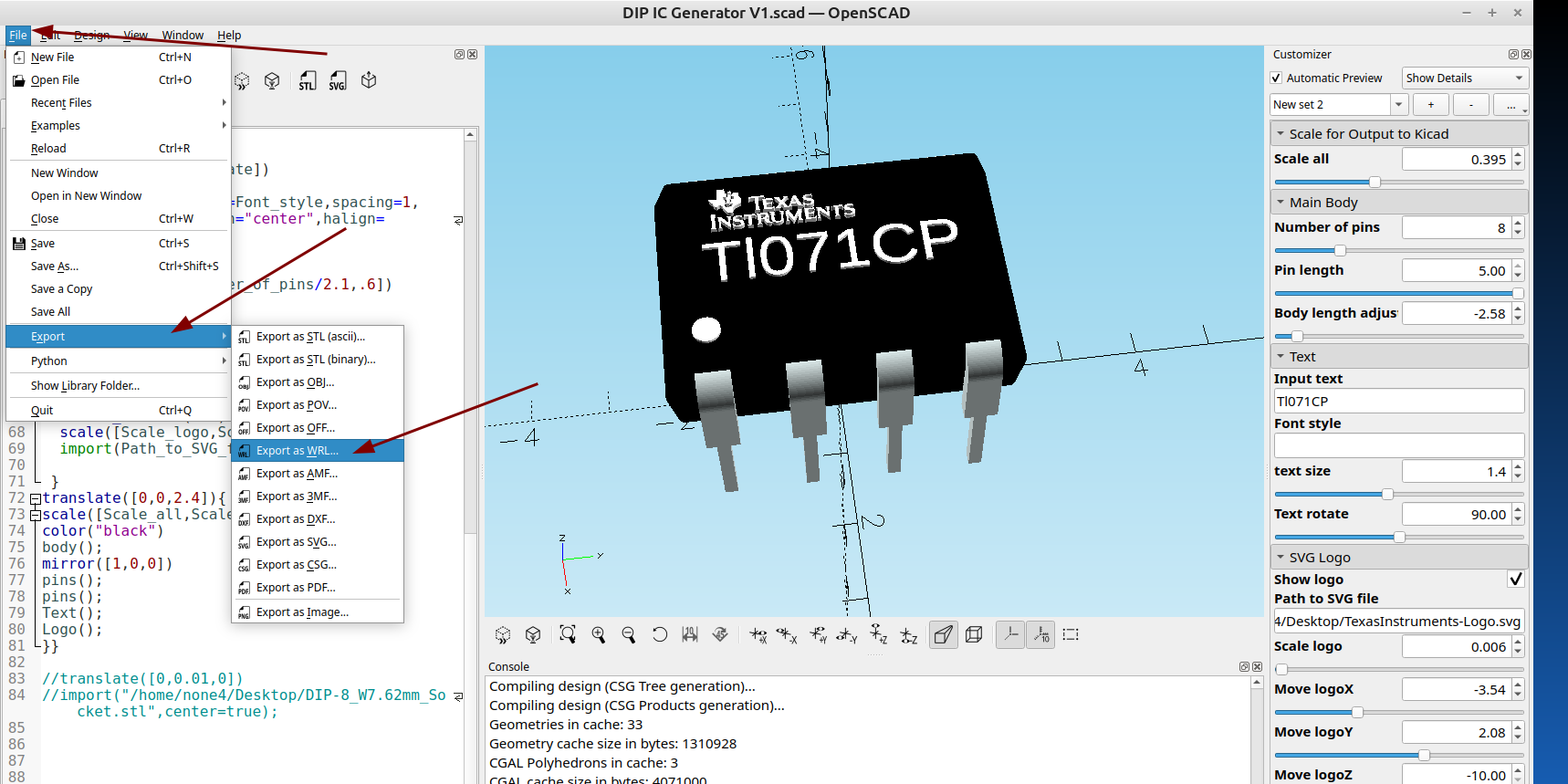
Once the file was rendered I exported it as a .WRL file so it can be imported into Kicad:
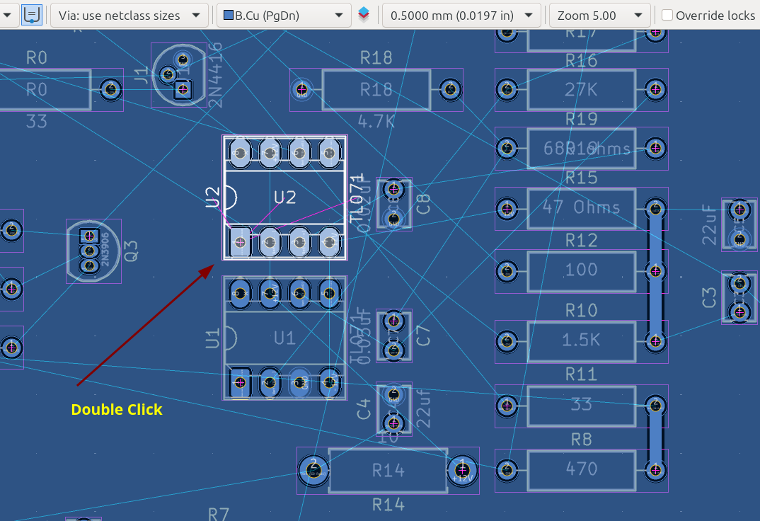
In the PCB editor double click on the outline of the component and a dialog will open:
Click the plus sign to add a new component:
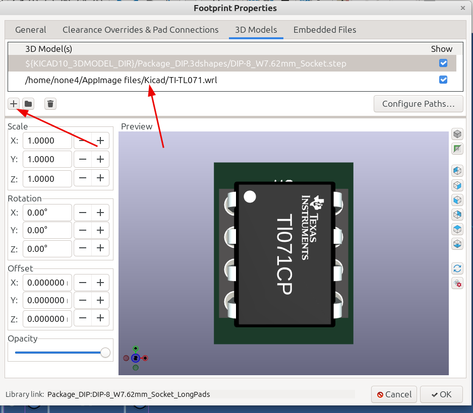
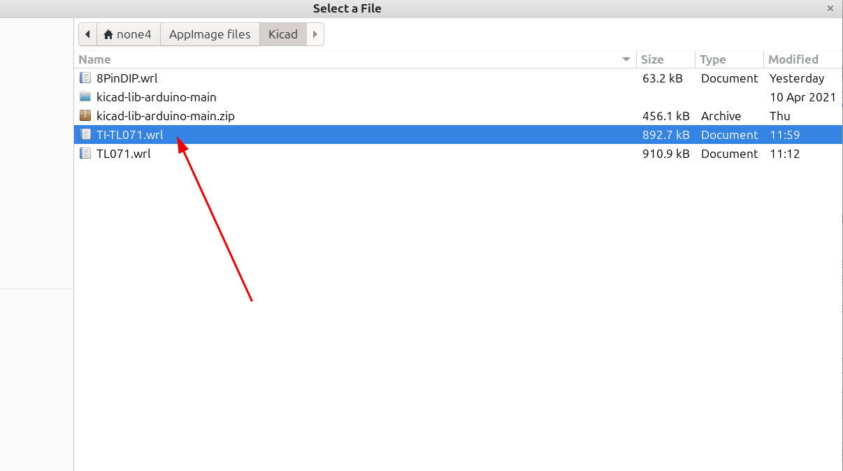
Then click the file Icon to open the folder location where you saved the file:
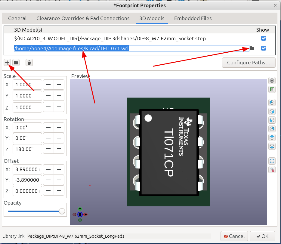
Once the file loads you can adjust the position with the selectors:
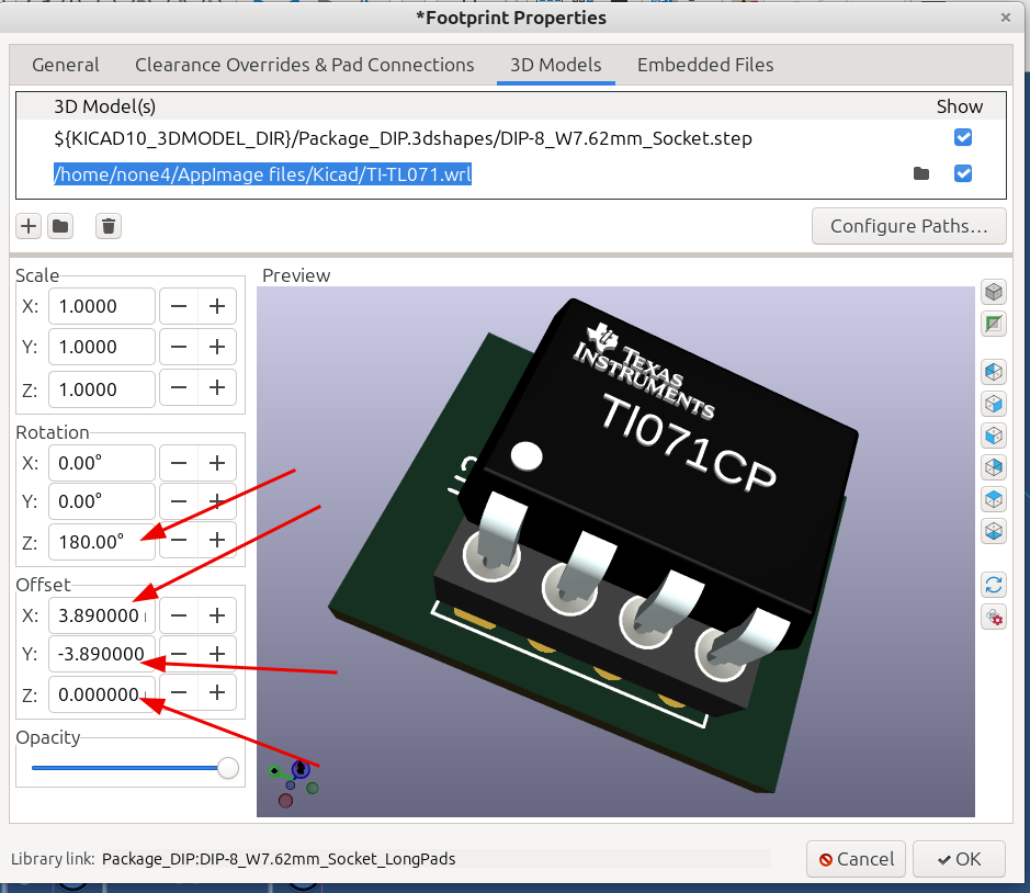
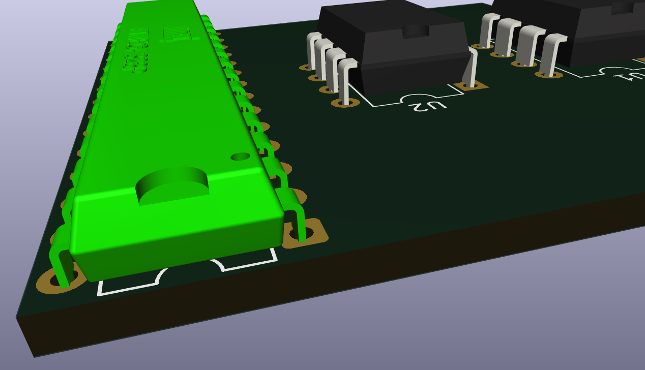
And now the space that was missing the component has a nice looking model that can be rendered:
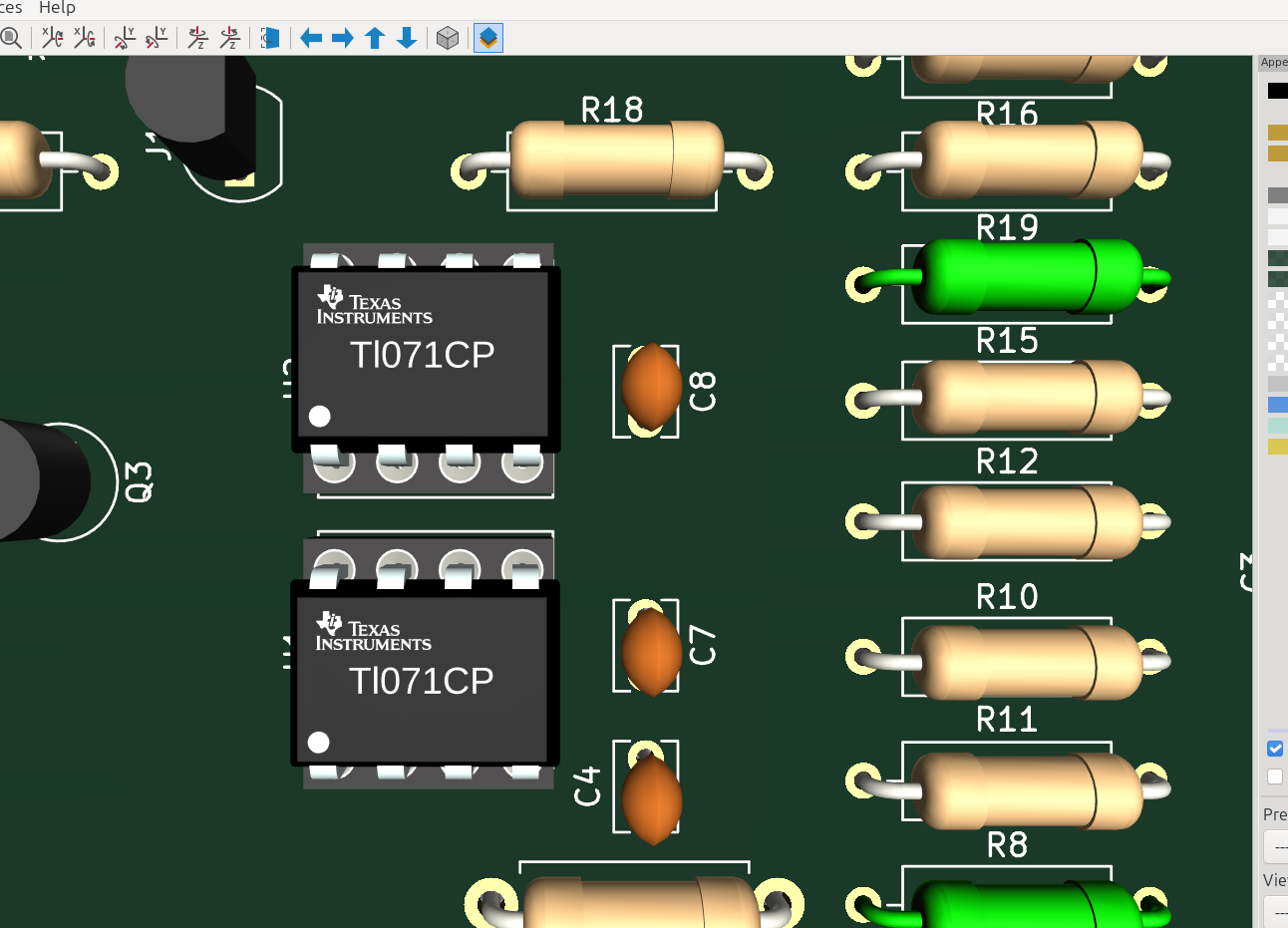
And that's how easy it is to make your own custom Component with OpenSCAD for Kicad. Notice that the resistors and transistors look pretty bare so of course I will be making a custom resistor and transistor generator also.