
3D Part design with OpenSCAD #151: Electronics enclosure helper Version 2
In post #121 I made a "project enclosure helper" that would allow you to select sides of a pcb board and extend them so the ports would fit nicely and are aligned when it is subtracted from a case, it needed some work so I made some improvements.
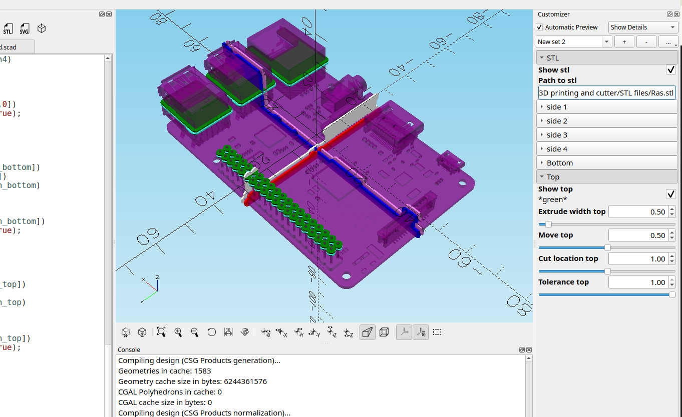
I modified the code so the selectors would be easier to see for alignment and made some things transparent so they stand out better.
here is the revised code:
//

/*[STL]*/
Show_stl=true;
Path_to_stl=("");

/*[side 1]*/
//*violet*//
Show_side1=true;
Extrude_width1=.5;//[.01:.01:30]
Cut_location1=1;//[-100:.01:100]
Move_side1=0;//[-100:.01:100]
Tolerance1=1;//[0:.01:1]

/*[side 2]*/
//*red*//
Show_side2=true;
Extrude_width2=.5;//[.01:.01:10]
Cut_location2=-1;//[-100:.01:100]
Move_side2=0;//[-100:.01:100]
Tolerance2=1;//[0:.01:2]

/*[side 3]*/
//*blue*//
Show_side3=true;
Extrude_width3=.5;//[.01:.01:10]
Cut_location3=-.5;//[-100:.01:100]
Move_side3=0;//[-100:.01:100]
Tolerance3=1;//[0:.01:1]

/*[side 4]*/
//*white*//
Show_side4=true;
Extrude_width4=.5;//[.01:.01:10]
Cut_location4=.5;//[-100:.01:100]
Move_side4=0;//[-100:.01:100]
Tolerance4=1;//[0:.01:1]

/*[Bottom]*/
//*Turquoise*//
Show_bottom=true;
Extrude_width_bottom=.5;//[.01:.01:10]
Move_bottom=-.5;//[-100:.01:100]
Cut_location_bottom=0;//[-100:.01:100]
Tolerance_bottom=1;//[0:.01:1]

/*[Top]*/
//*green*//
Show_top=true;
Extrude_width_top=.5;//[.01:.01:10]
Move_top=.5;//[-100:.01:100]
Cut_location_top=1;//[-100:.01:100]
Tolerance_top=1;//[0:.01:1]


module side1(){
if (Show_side1)
color("violet")
rotate([-90,0,0])
translate([0,0,-Cut_location1])
translate([0,0,-Move_side1])
linear_extrude(Extrude_width1)
fill()
offset(Tolerance1)
projection(cut=true)
rotate([90,0,0])
translate([0,Cut_location1,0])
import(Path_to_stl,center=true);
}

module side2(){
if (Show_side2)
color("red")
rotate([-90,0,90])
translate([0,0,-Cut_location2])
translate([0,0,-Move_side2])
linear_extrude(Extrude_width2)
fill()
offset(Tolerance2)
projection(cut=true)
rotate([-90,90,180])
translate([-Cut_location2,0,0])
import(Path_to_stl,center=true);
}

module side3(){
if (Show_side3)
color("blue")
rotate([-90,0,0])
translate([0,0,-Cut_location3])
translate([0,0,-Move_side3])
linear_extrude(Extrude_width3)
fill()
offset(Tolerance3)
projection(cut=true)
rotate([90,0,0])
translate([0,Cut_location3,0])
import(Path_to_stl,center=true);
}

module side4(){
if (Show_side4)
color("white")
rotate([-90,0,90])
translate([0,0,-Cut_location4])
translate([0,0,-Move_side4])
linear_extrude(Extrude_width4)
fill()
offset(Tolerance4)
projection(cut=true)
rotate([-90,90,180])
translate([-Cut_location4,0,0])
import(Path_to_stl,center=true);
}

module bottom(){
if (Show_bottom)
color("Turquoise")
translate([0,0,Cut_location_bottom])
translate([0,0,-Move_bottom])
linear_extrude(Extrude_width_bottom)
fill()
offset(Tolerance_bottom)
projection(cut=true)
translate([0,0,-Cut_location_bottom])
import(Path_to_stl,center=true);
}

module top(){
if (Show_top)
color("green")
translate([0,0,Cut_location_top])
translate([0,0,Move_top])
linear_extrude(Extrude_width_top)
fill()
offset(Tolerance_top)
projection(cut=true)
translate([0,0,-Cut_location_top])
import(Path_to_stl,center=true);
}

side1();
side2();
side3();
side4();
bottom();
top();

if(Show_stl)
color("purple",.5)
import(Path_to_stl,center=true);
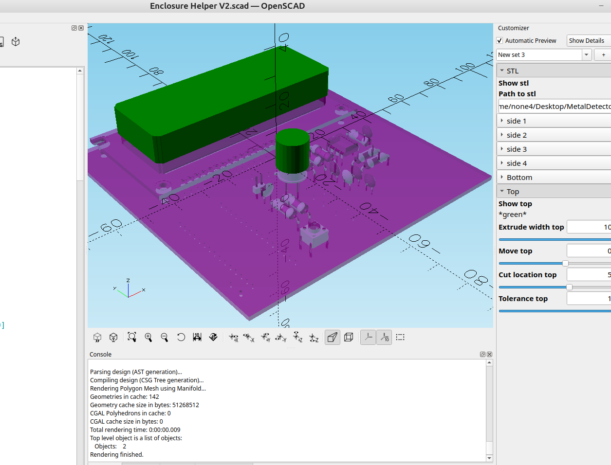
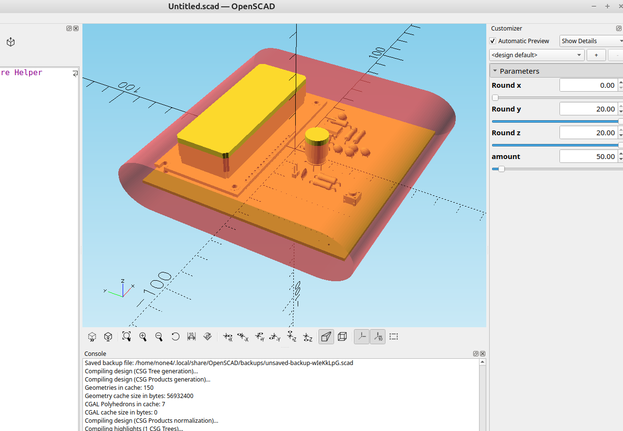
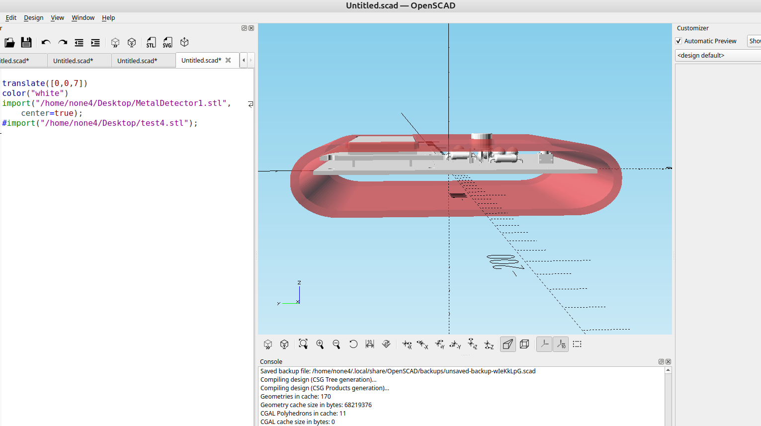
now it is much easier to see what side is selected by color and where they are at for adjustment:
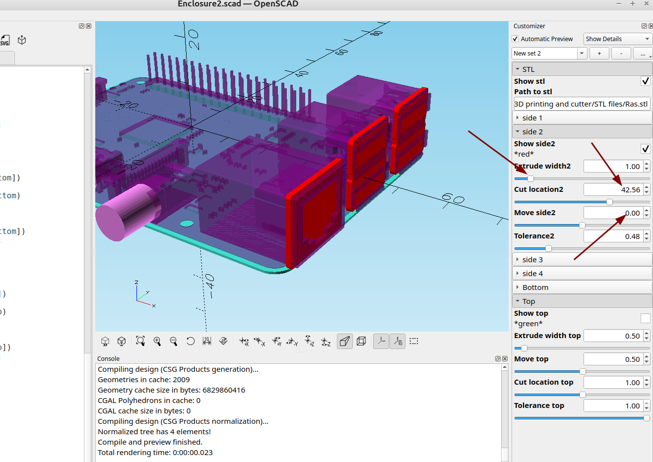
in the above example I set the extrude with to 1mm, moved the side parameter to zero and then slowly adjusted the cut location until it was where I needed it.
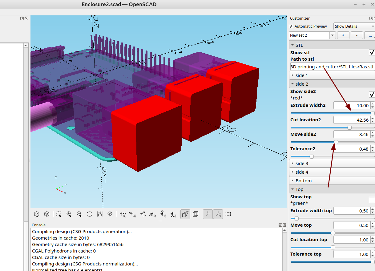
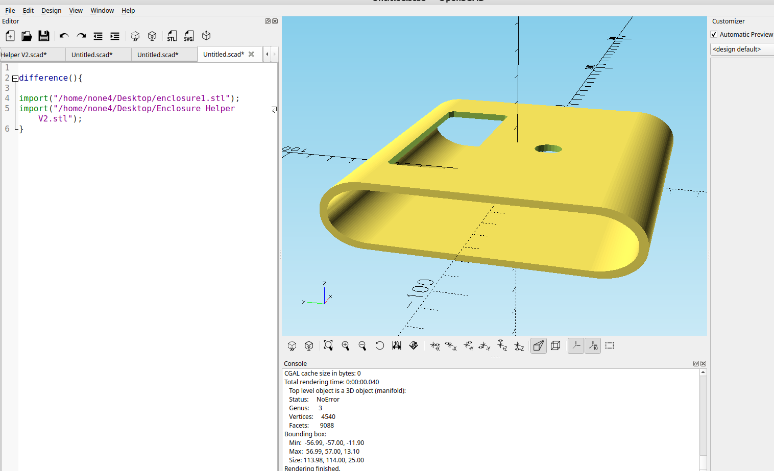
Once it was where I wanted it I adjusted the extrude width and moved it so it would extend past the side of the enclosure so I can use difference() to make a nice cut out for the ports or a display:
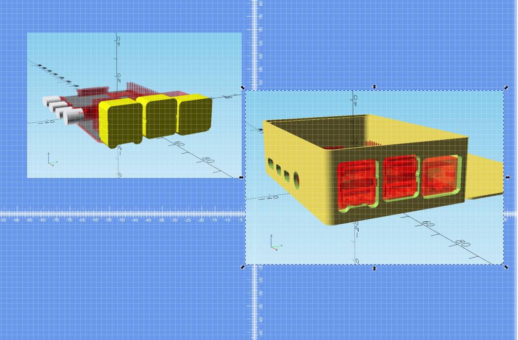
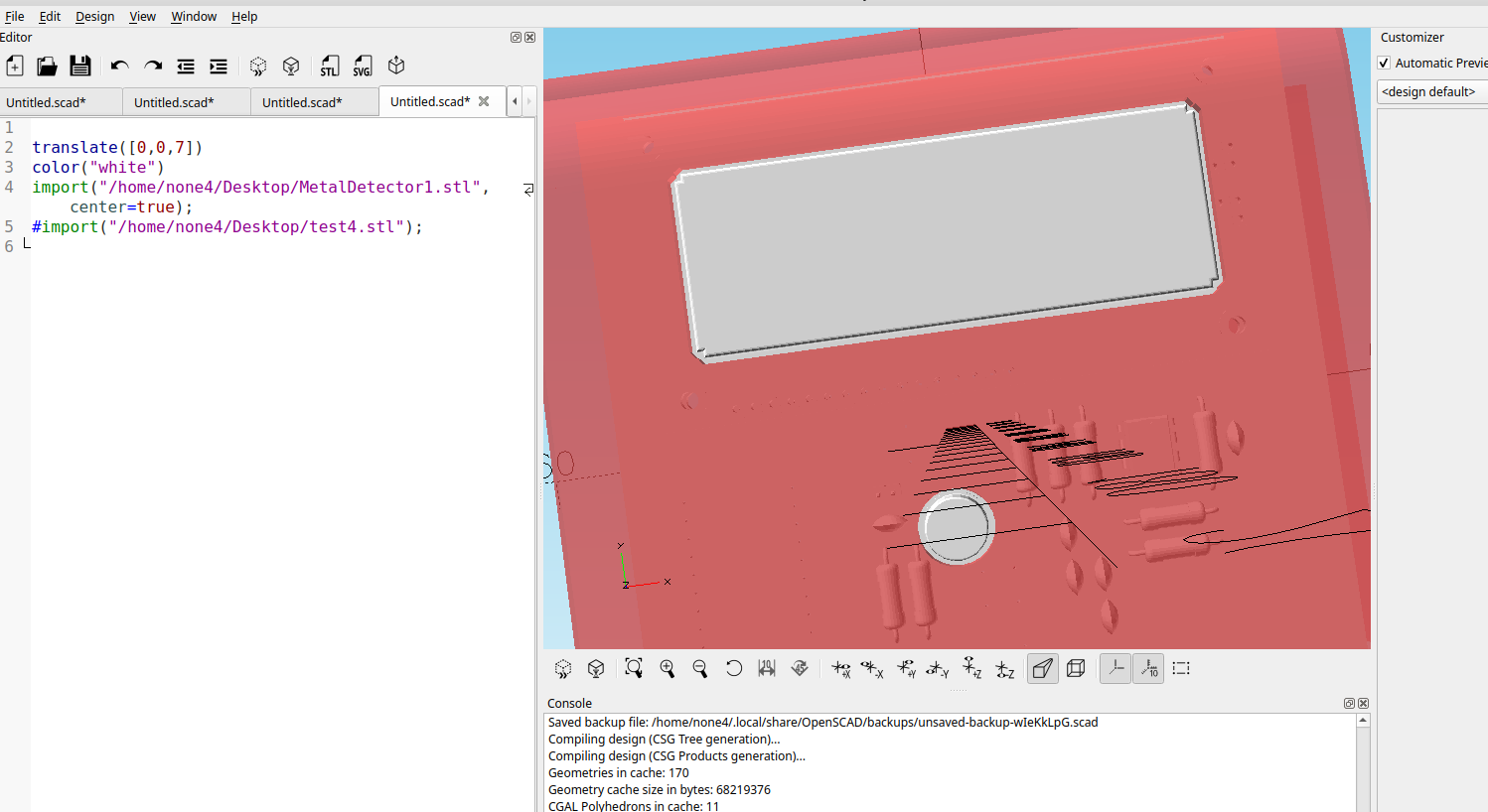
As an example here is an Arduino project I made with Kicad:
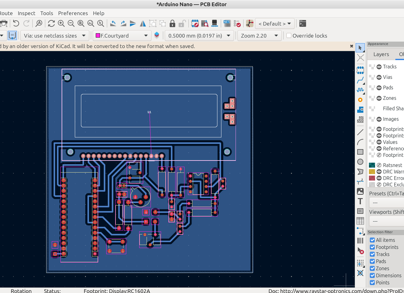
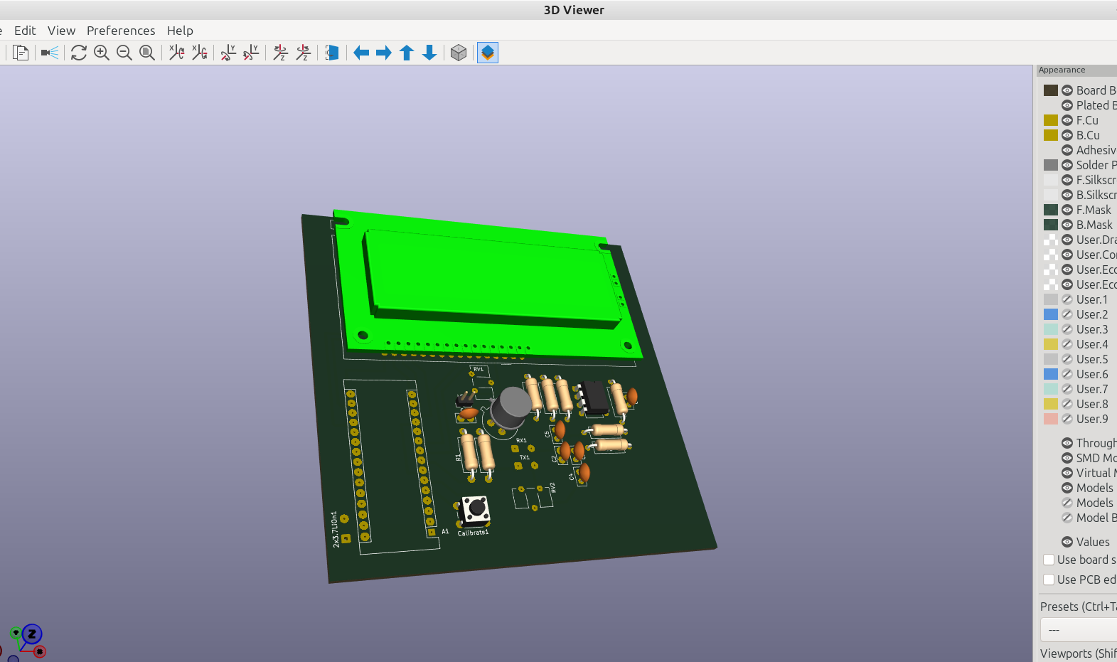
After exporting the board from Kicad I used the enclosure helper to make a block out for the display and the sensor:
Here is the other post where I show how I made the case for this example:
After I made the case fit the board I loaded it and the helper board and performed a difference to make a hole for the display:
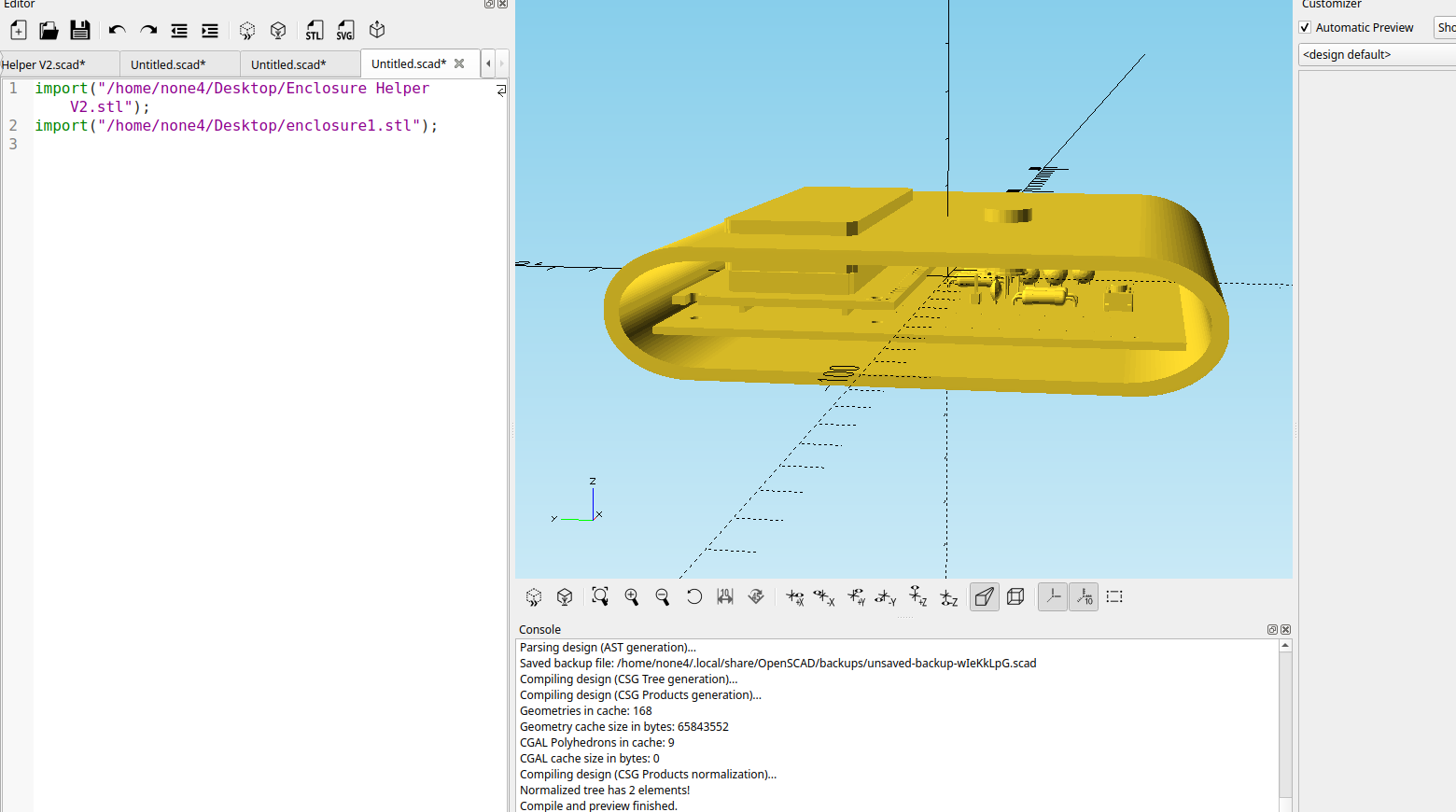
Then I loaded it and the original board to see if it looks like the display and sensor will have a nice fit:
I have a few more ideas to make this even more usable and I will be making another post about it in the near future.