
3D part design with Inkscape and Openscad part 4: Measurements and precision
An example of how to set the range precision in the OpenSCAD customizer.
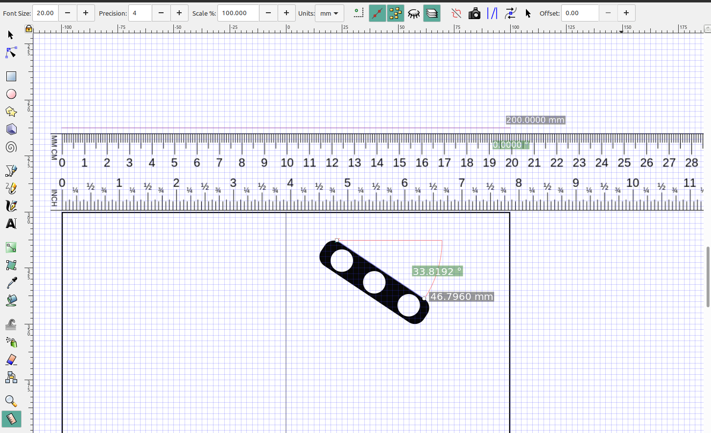
In this tutorial I will make a small tire and demonstrate the measuring tool in Inkscape and the level of precision you can make your designs in Openscad.
I like to set the mouse wheel to zoom so I can get really close and check the alignment of the elements of my design:
I'm going to make the center part of the tire and then add some treads and a 5mm hole in the center:
Then I will convert the object to a path, add nodes and make them lines:
Output the file to .dxf:
Open the drawing in openscad, extrude it to the proper height and add some twist to the treads:
You will notice that the treads have lines in them that don't smooth out when I increase the slices, that's because I only added a few extra nodes in Inkscape, the more nodes the finer the details but the longer it takes to render the files. Since I have the drawing up in inkscape I can easily go back and add more if I needed to.
In the customizer you can set the precision of the sliders:
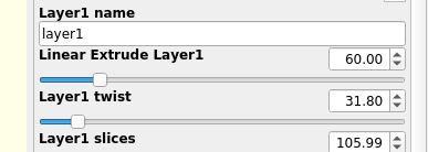
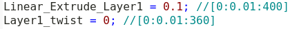
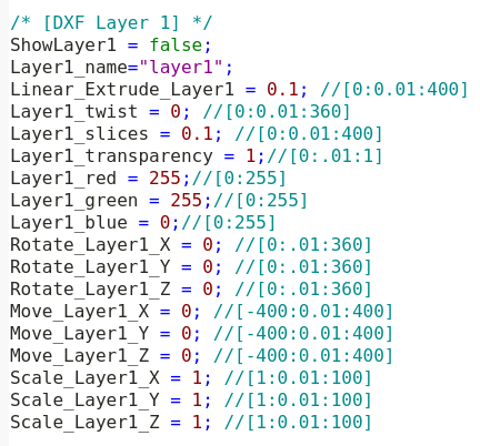
In the brackets are the numbers that specify the start, resolution and end of the slider, you can change that to .001 if you wanted to. As you can see in the customizer set up I have the scale and resolution set to the max size of the printer 0 to 400, 0 to 360 degrees for rotate and scaling of the object set 1 to 100%
In part 5 I am going to make a more complex object and add extra capabilities to modify my design using the customizer in Openscad.