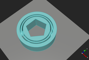
Using Inkscape to design a bearing is pretty easy, here is the process I used to make a bearing with extra channels to insert a wire raceway in the bearing.
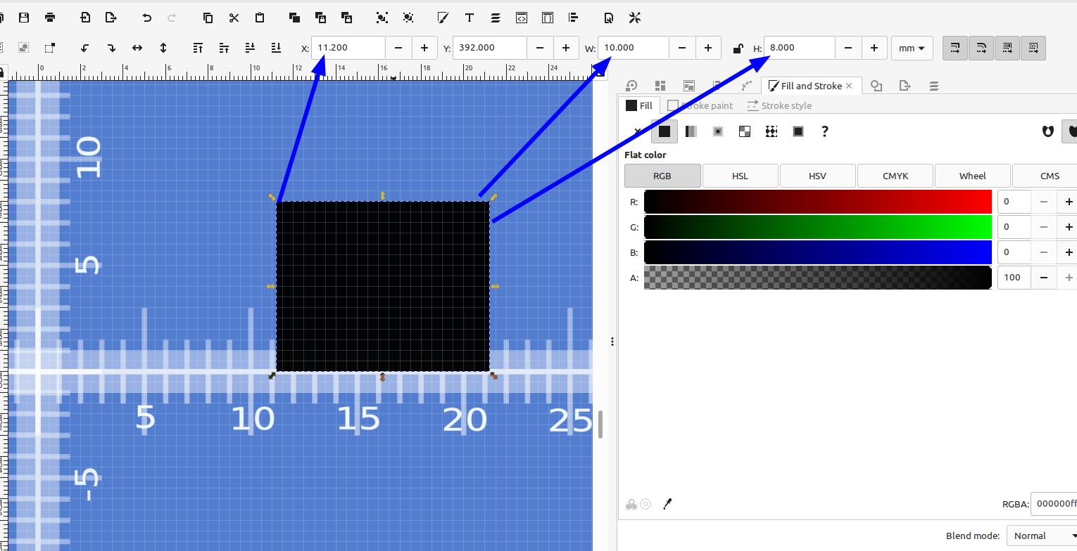
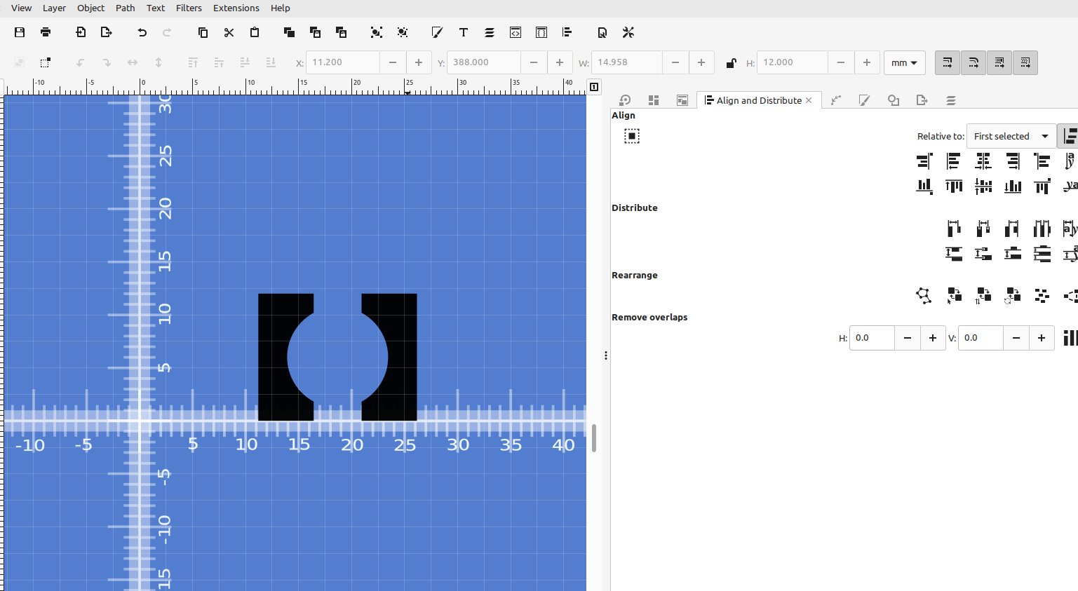
First I made a rectangle the height and width I needed the bearing to be, and located it so when I used rotate extrude the center hole in my bearing was the right size.
Next I made a circle the size of my ball bearing and a rectangle centered with it for the slot in the bearing.
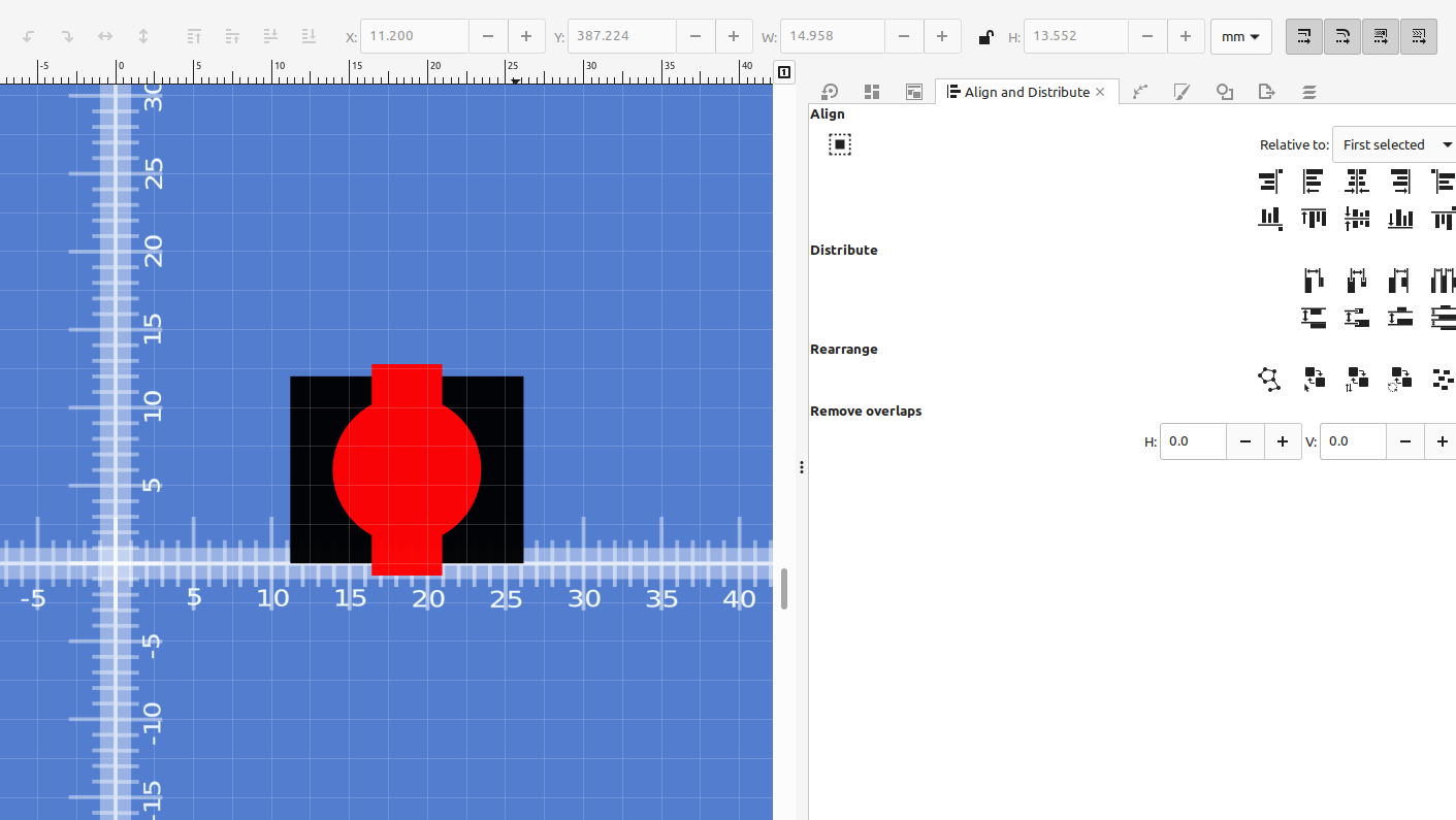
I aligned everything and used Path>Difference to subtract the bearing from the race.
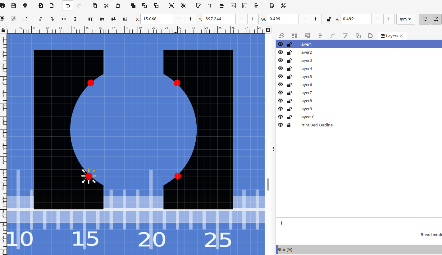
Then I added the slots for the wire raceway using the same method.
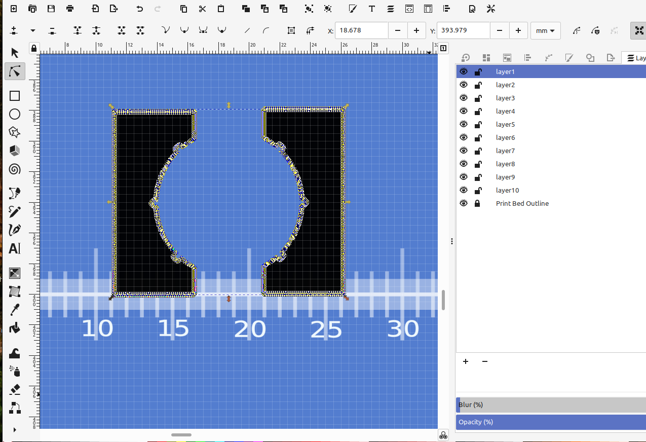
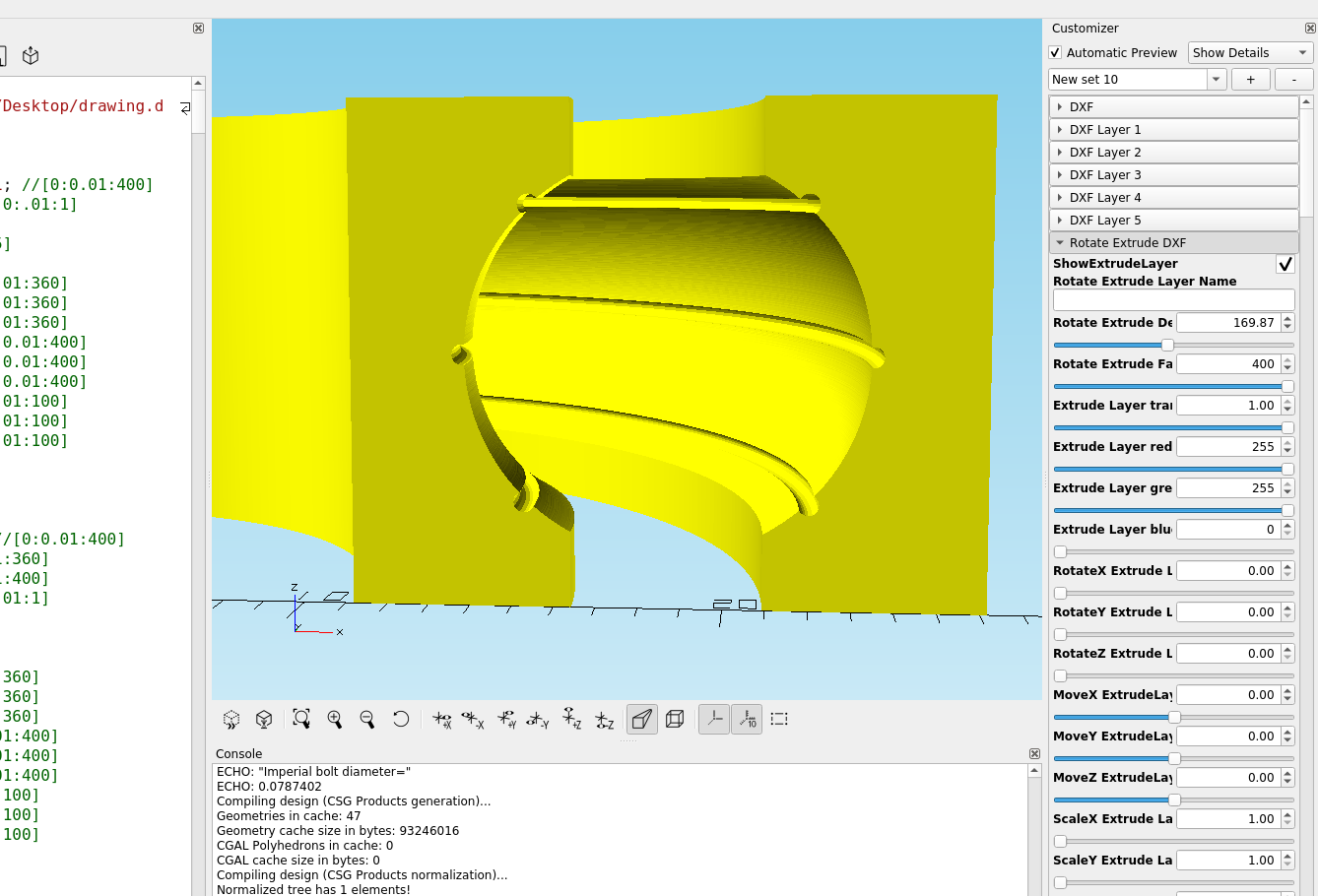
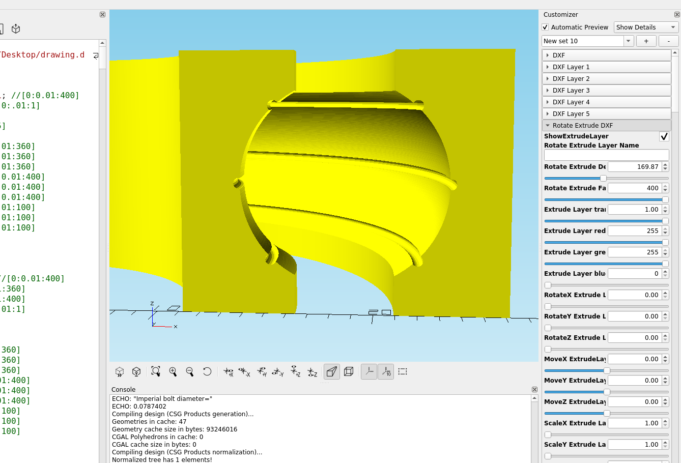
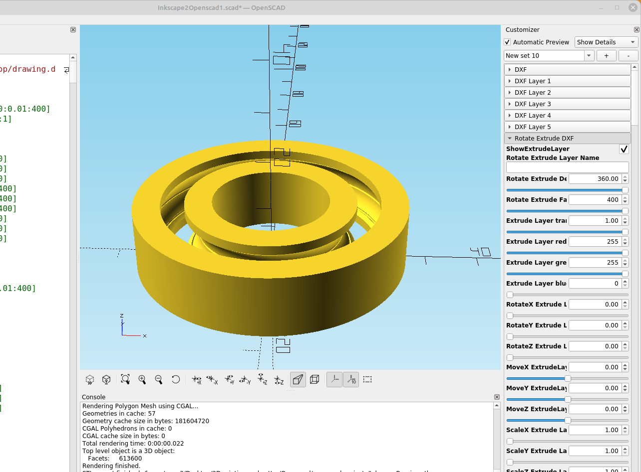
Then I imported the dxf file into Openscad and used rotate extrude to make the bearing.
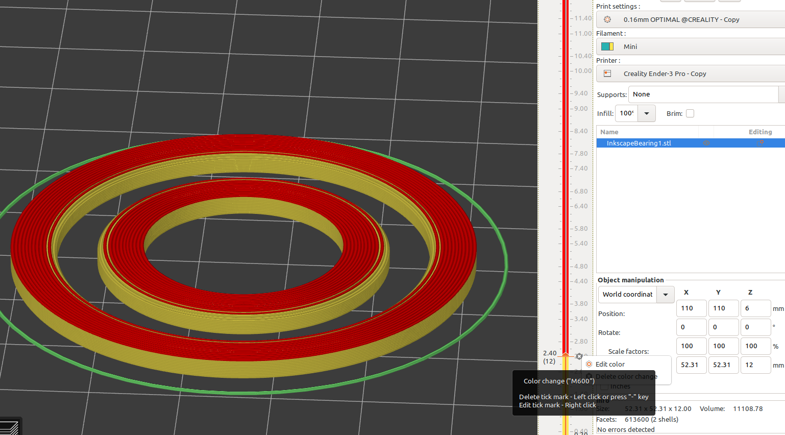
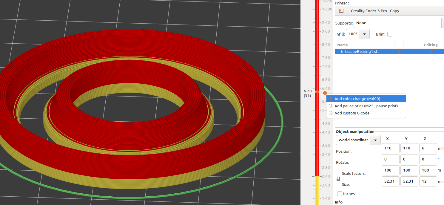
In order to add the races and bearings, you need to use your slicer and stop the print at the correct layer, here I am using Prusa Slic3r and adding a filament change at the correct heights, GCODE M600 pauses the print and move the print head, then allows you to resume after the races or bearings are installed, this may be different depending on your printer and firmware. Most printers use standard gcode commands: https://marlinfw.org/docs/gcode/M600.html
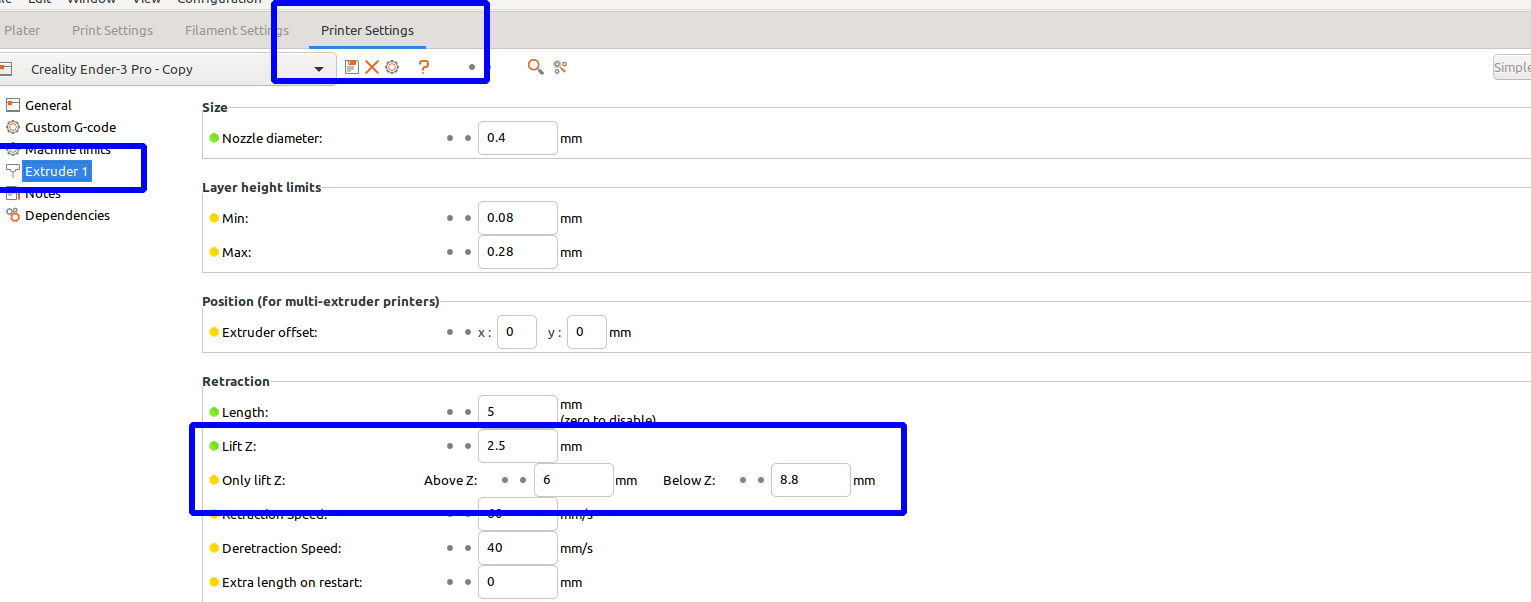
Additionally you will need to set the z-hop settings to lift the print head over the bearings, I set mine to 1/2 the size of my ball bearing, and the layer I want the z-hop to start and end and it works pretty well:
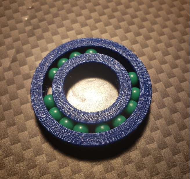
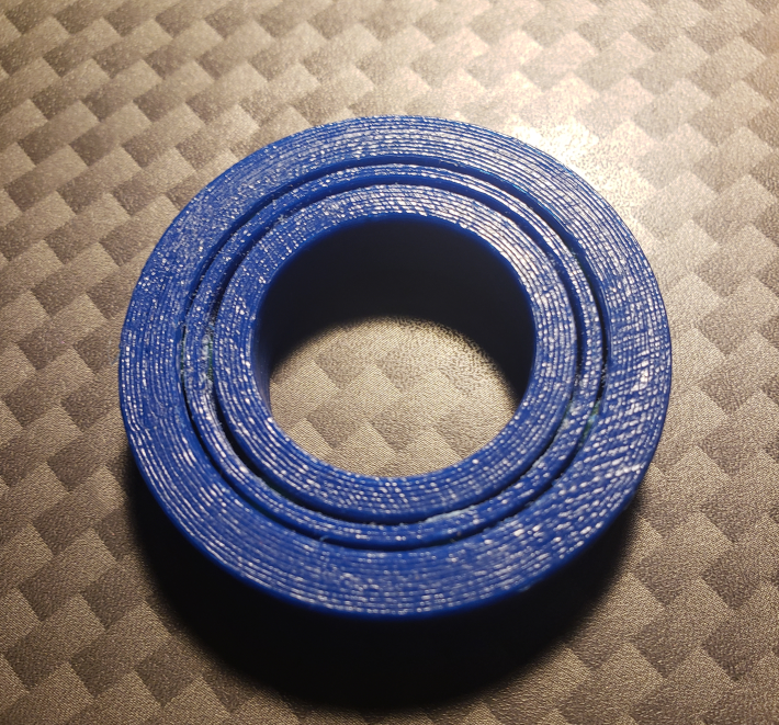
A bearing that was "printed in place" and ball bearings added as it was printed. It had pretty close tolerances, too close and the sections will fuse together, about a .75 mm clearance was the best I could get at .20 mm layer height. It's a little tight but fully functional:
Here is a link to videos on how to make wire raceways for 3d printed bearings: https://www.youtube.com/c/ErosNicolau
