3D part design with Openscad #37: ball bearing grid
Using Openscad to make a ball bearing grid.
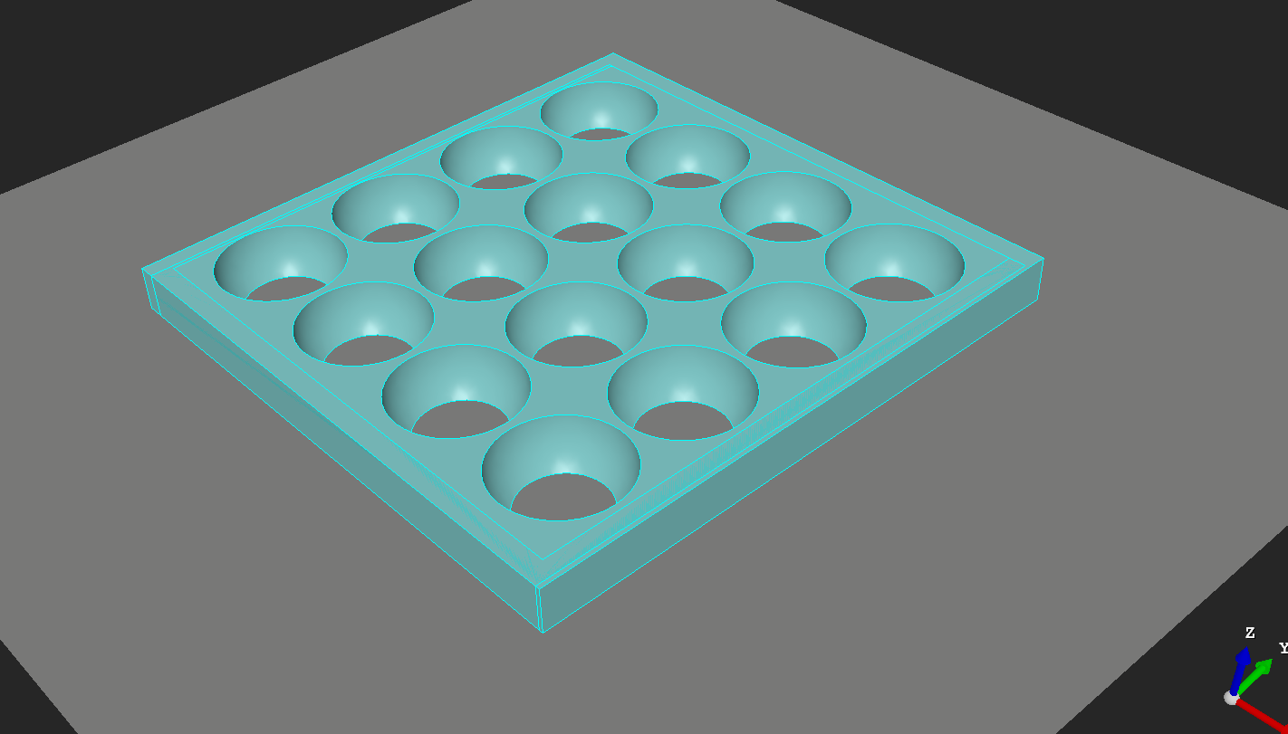
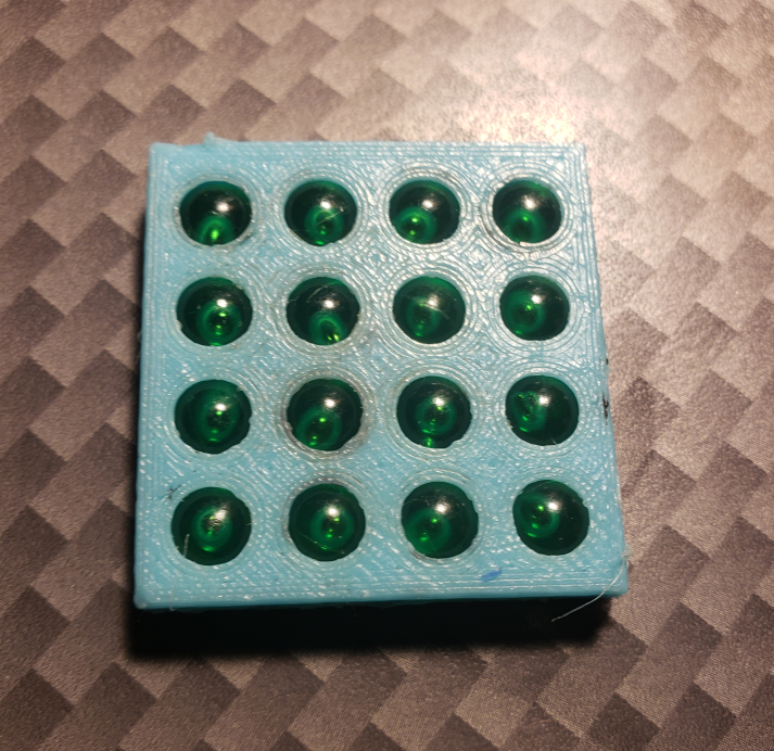
While I was making the bearing module I thought it might be handy to make a flat bearing, so I made a couple of modules that I can make an adjustable grid for the ball bearings to sit in with an adjustable frame around it.
Here is the code:
Sphere_size = 1  ;//[1:.01:100]
X_number = 4  ;//[1:1:100]
Y_number = 4  ;//[1:1:100]
Cell_spacing = 1 ;//[.5:.01:100]
X_spacing= 4  ;//[1:.01:100]
Y_spacing = 4  ;//[1:.01:100]
Tray_depth = .25  ;//[.1:.01:10]
Frame_depth = .50  ;//[-1:.01:10]
Move_tray_x = -2.1  ;//[-100:.01:100]
Move_tray_y = -3.64  ;//[-100:.01:100]
Move_tray_z = 0  ;//[-100:.01:100]
Move_grid_x = 0 ;//[-100:.01:100]
Move_grid_y = 0 ;//[-100:.01:100]
Move_grid_z = 0 ;//[-100:.01:100]


module Grid(){
  translate([Move_grid_x,Move_grid_y,Move_grid_z])

for(x=[0:X_number-1]){
   translate([x*Cell_spacing*X_spacing,0,0])
   rotate([0,0,90])
for(y=[0:Y_number-1]){
  translate([y*Cell_spacing*Y_spacing,0,.5*Sphere_size])

  sphere(Sphere_size/2,$fn=40);
}}}

module Tray(){
  translate([Move_tray_x,Move_tray_y,Move_tray_z])
  cube([X_number*X_spacing+1,Y_spacing*Y_number+2,Tray_depth],center=false);
}

module Frame(){
  translate([Move_tray_x-.8,Move_tray_y,Move_tray_z])

difference(){

cube([X_spacing*X_number+2,Y_spacing*Y_number+3,Tray_depth+Frame_depth]);
translate([1,1,0])
cube([X_spacing*X_number,Y_spacing*Y_number+1,Tray_depth+12]);
}}


difference(){
Tray();
Grid();
}

Frame();
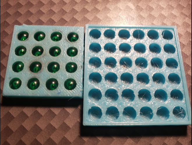
I made two halves to keep the balls captive and welded them together with the extruder tip: