3D part design with OpenSCAD and FreeCad # 158: Modifying the resistor code so it's easier to convert the resistor to a step file.

After converting the files made with the resistor generator to a step file I noticed it was almost impossible to get the color bands separated from the main body so I made some changes.
Here is the updated code:
//

// 7/7/2026 Resistor Calculator and 3D model generator Version 7 by Infintyplays.com
// License- Public Domain

/*[Resize for Kicad]*/
Resize=5.30;//[2.65:2.65:26.5]

/*[ Enter resistor Value ]*/
Show_values=true;
Show_main_body=true;
Resistor_value=100;

/*[Color Band Select]*/
Show_color_bands=true;
band_1="Brown";//[Black,Brown,Red,Orange,Yellow,Green,Blue,Violet,Grey,White,Gold,Silver]

band_2="Black";//[Black,Brown,Red,Orange,Yellow,Green,Blue,Violet,Grey,White,Gold,Silver]

band_3="Brown";//[Black,Brown,Red,Orange,Yellow,Green,Blue,Violet,Grey,White,Gold,Silver]

band_4="Gold";//[Silver]

/*[leads]*/
lead_length=4;//[2:.01:6]
lead_diameter=.40;//[.1:.01:.6]

/*[Hidden]*/
$fa=$preview? 2:1;;
$fs=$preview?.2:.1;;
//$fn=$preview? 60:90;;


color_names=["Black","Brown","Red","Orange", "Yellow","Green","Blue","Violet","Grey","White","Gold","Silver"];

color_rgb=[[0.2,0.2,0.2],[0.4,0.25,0.13],[0.9,0.1,0.1],[1,0.5,0],[0.9,0.9,0],[0.1,0.7,0.1],[0.1,0.1,0.9],[0.6,0.1,0.7],[0.5,0.5,0.5],[0.95,0.95,0.95],[0.8,0.6,0.2],[0.75,0.75,0.75]];

function get_index(name)=search([name],color_names)[0];

function get_color(name)=color_rgb[get_index(name)];

function get_multiplier(index)=
    (index==10)?0.1:
    (index==11)?0.01:
    pow(10,index);
    d1=get_index(band_1);
    d2=get_index(band_2);
    mult=get_multiplier(get_index(band_3));
    ohms=(d1*10+d2)*mult;

label_text=
    (ohms>=1000000)?str(ohms/1000000,"M Ohm") :
    (ohms>=1000)?str(ohms/1000,"k Ohm") :
    str(ohms," Ohm");

function get_color2(val) =
  val == 0 ? "black":
  val == 1 ? "brown":
  val == 2 ? "red":
  val == 3 ? "orange":
  val == 4 ? "yellow":
  val == 5 ? "green":
  val == 6 ? "blue":
  val == 7 ? "violet":
  val == 8 ? "gray":
  val == 9 ? "white":
  val == "gold"?"gold":
  val == "silver"?"silver":band_4;
Tolerance="silver";//[gold]


module Text(){
translate([0,1+(Resize/10),0]){
  color("grey"){
  linear_extrude(.1)
  text(label_text, size=1,halign="center",valign="center",spacing=1.1);
}}}

module band_ring(z_pos){
if(Show_color_bands)
  translate([0,0,z_pos]) {
  cylinder(h=1,r=1.03,center=false);
}}

module resistor_3d(b1,b2,b3,b4){
 color(get_color(b1))band_ring(z_pos=-2.3);
 color(get_color(b2))band_ring(z_pos=-1.0);
 color(get_color(b3))band_ring(z_pos=0.3);
 color(get_color(b4))band_ring(z_pos=2.2);
}

module auto_resistor(ohms,tolerance=band_4){
  raw_exp=floor(log(ohms)/log(10));
  sig_digits=round(ohms/pow(10,raw_exp-1));
  d1=sig_digits>=100?floor(sig_digits/100):floor(sig_digits/10);
  d2=sig_digits>=100?floor((sig_digits % 100)/10) :floor(sig_digits%10);
  mult=sig_digits>=100?raw_exp:raw_exp-1;
  colors=[get_color2(d1),get_color2(d2),get_color2(mult),get_color2(tolerance)];
  echo (colors);

for(i=[0:3]){
  band_offset=-15/2.7+(i);
  translate([-1,0,band_offset+4]){
  rotate([270,180,0])
  translate([0,0,])
  color(colors[i])
  linear_extrude(.075)
  text(colors[i],size=.5,halign="left",valign="bottom",spacing=1.1);
}}}

module main_body(){
if(Show_main_body)
 color("khaki"){
 minkowski(){
 translate([1.9,0,0])
 rotate([0,90,0])
 cylinder(5,.01,.01);
 sphere(1);
}
 translate([1.6,0,0])
 sphere(1.05);
 translate([7.5,0,0])
 sphere(1.05);
}}

module leads(){
rotate([90,90,90])
color("lightgrey"){
  translate([0,0,2]){
  rotate([90,180,0])
  translate([-2,5,0])
  rotate_extrude(90)
  translate([2,0,0])
  circle(r=lead_diameter);
  rotate([90,180,90])
  translate([0,7,2])
  cylinder(lead_length,lead_diameter,lead_diameter);
}
  translate([0,0,-1]){
  rotate([270,180,0])
  translate([-2,5,0])
  rotate_extrude(90)
  translate([2,0,0])
  circle(r =lead_diameter);
  rotate([90,180,90])
  translate([0,-7,2])
  cylinder(lead_length,lead_diameter,lead_diameter);
}}}

resize([Resize,0,0],auto=true){
translate([-.5,0,0]){
rotate([0,90,0])
resistor_3d(band_1,band_2,band_3,band_4);
color("khaki")
translate([-4,0,0])
main_body();
leads();
}}

if(Show_values){
%rotate([90,0,90])
%auto_resistor(Resistor_value);
%Text();
}


echo(str(ohms));
This is still a work in progress and I am going to make a bunch of changes but for now it is a work around, the good news is once you have the two step files saved > one for the bands and one for the main body, you don't have to do anything but change the band colors to the colors you need the next time, so you really only have to go through this process once.
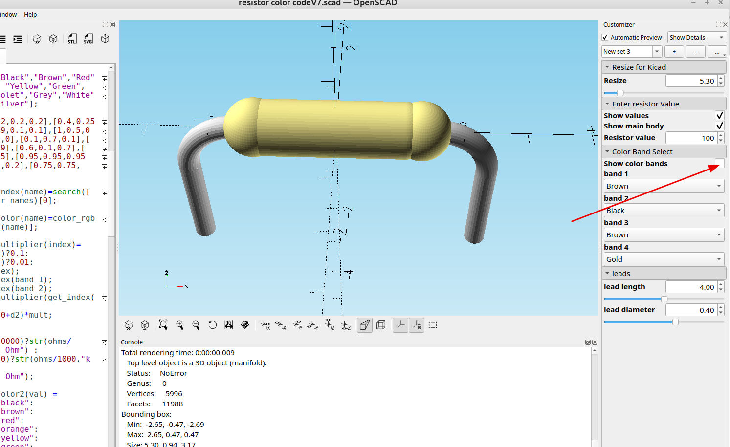
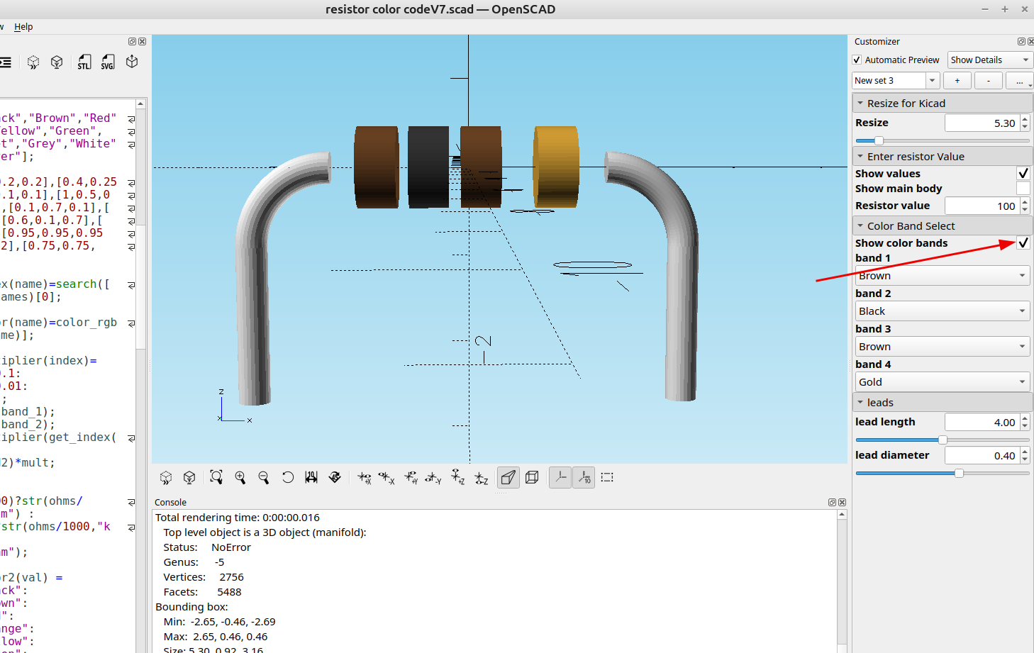
I added a check box to hide the color bands or hide the main body:
I also reduced the number of facets to a usable number so it doesn't take as long to convert in FreeCad, it still takes a few seconds to run the macro (about 8 seconds on my machine) but you can reduce the number even more by changing the values for $fa if you are getting timeout errors or FreeCad seems to hang for a long time, it always finishes but with a large number of facets it takes a long time.
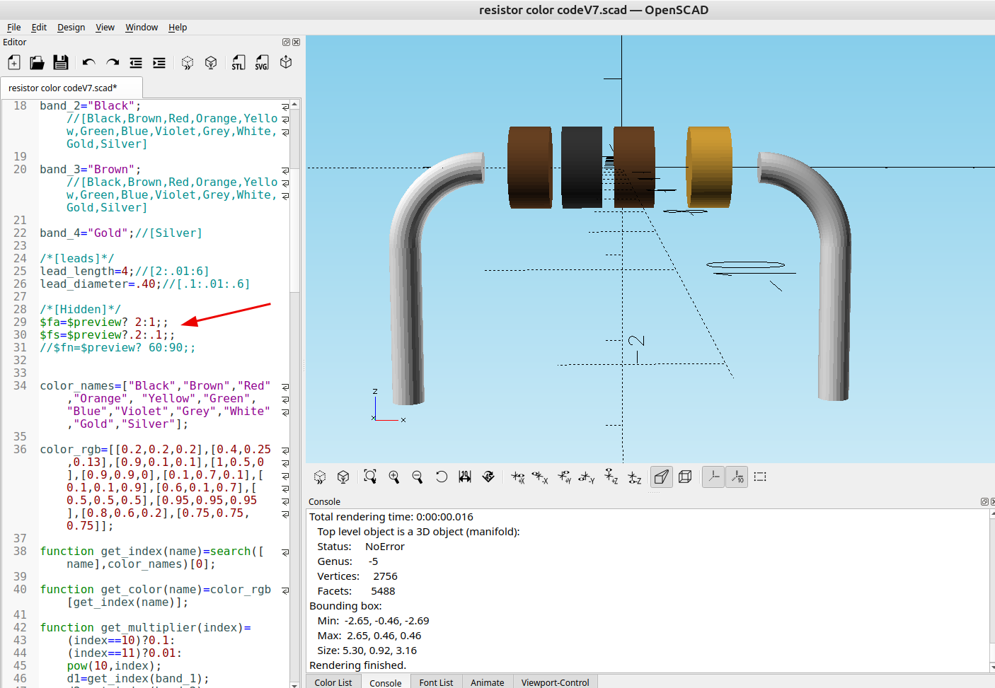
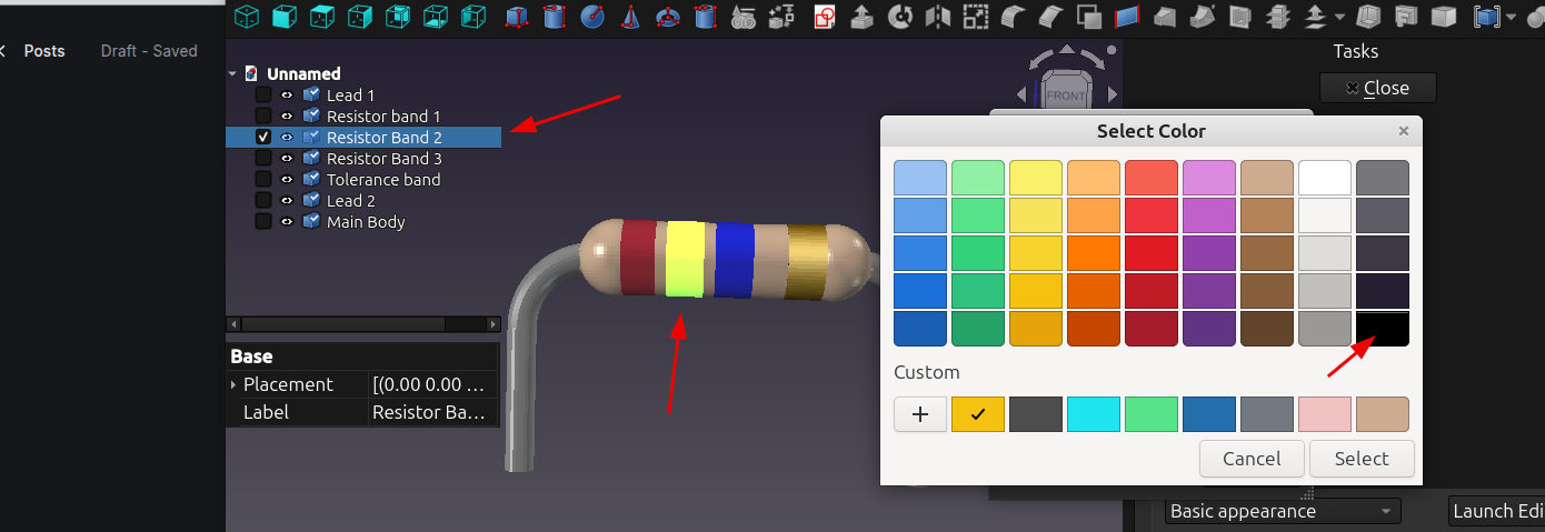
After I saved the two stl files (one for the main body and one for the bands) and converted them to step files with Freecad, I re-imported them back into Freecad as one .step object then renamed the individual sections so they are easy to identify and now the sections can be selected and the colors changed:
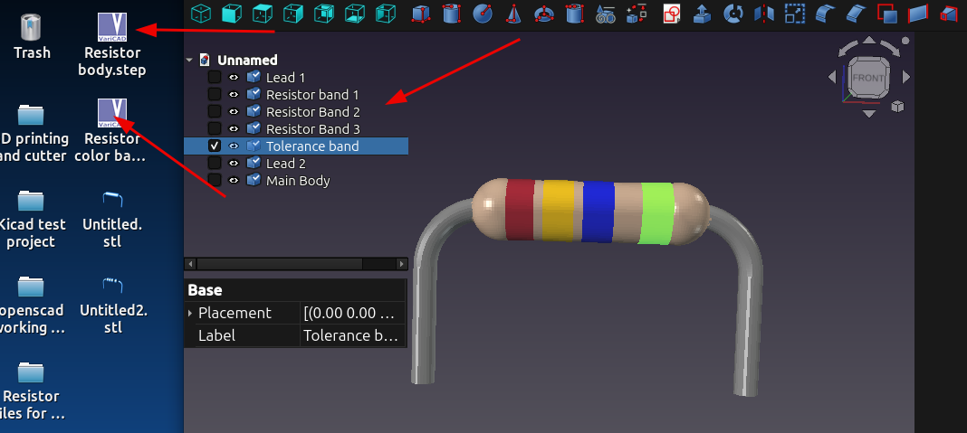
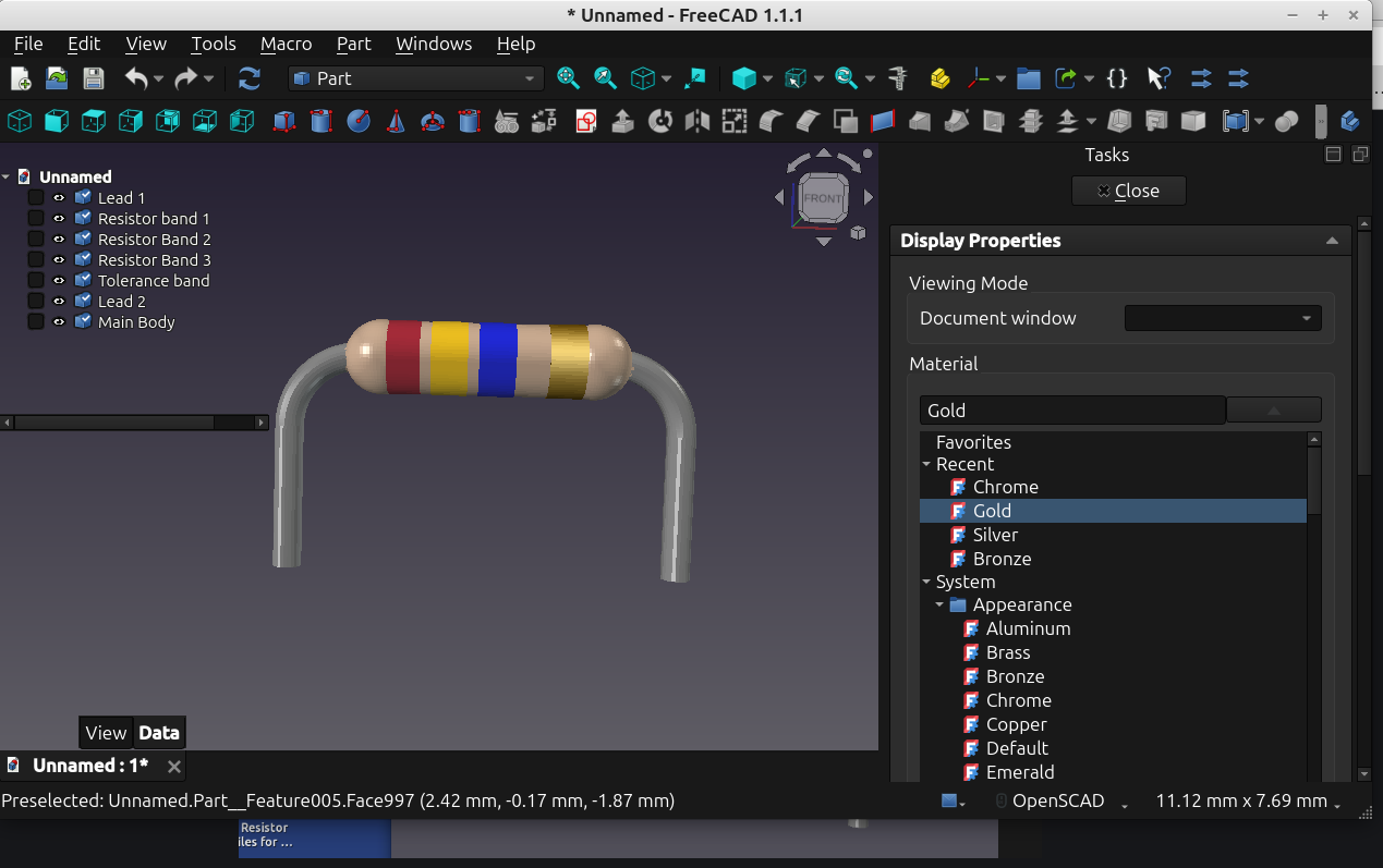
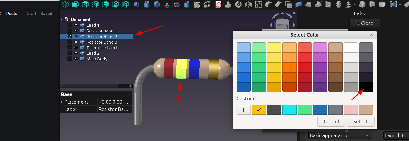
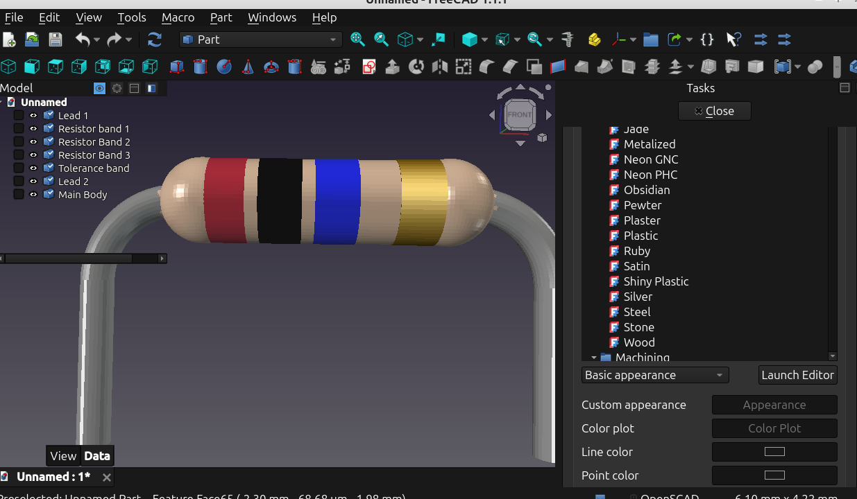
It's pretty easy to just design a resistor from scratch with FreeCad but it was also pretty easy to just convert the files made with OpenSCAD, and if you are new to Freecad doing things like this is a good way to learn the program.