3d part design with OpenSCAD #154: An automatic resistor color code calculator and model generator. (updated)

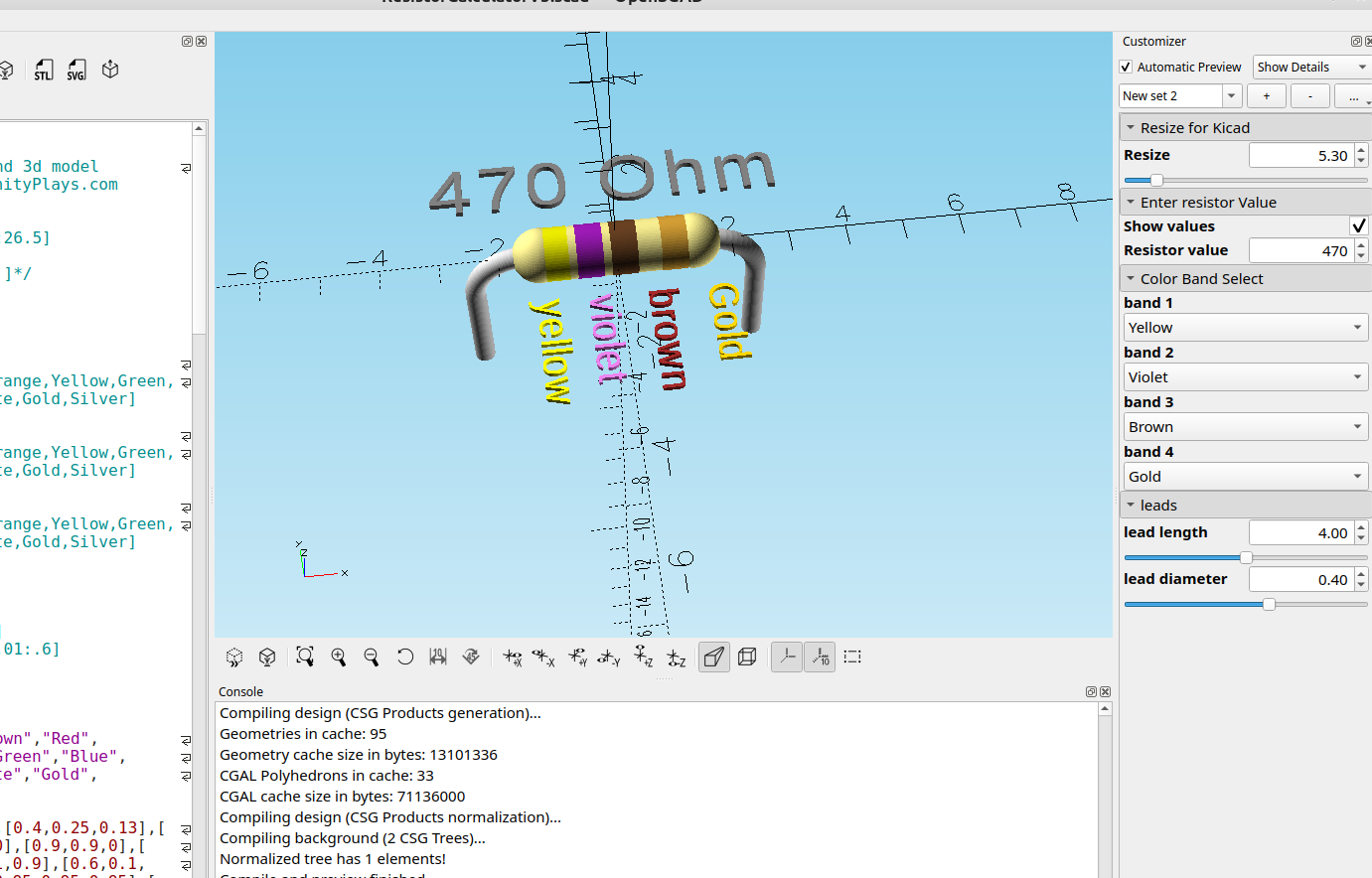
In the last post I made a resistor model generator that you could manually change the values of the bands for specific resistor values, this updated code will automatically change the colors based on the input of the resistor value and output a model that can be used in Kicad.
Note: I made some changes by combining the two calculators so you can either select the color bands or input a resistor value, I'm still working on getting the color bands to change automatically when either the value is entered or they are selected with the color selectors, as it is if you enter a value it will display the colors and then you have to change the color selectors to match and it will update the resistor to the right colors.
Update: there are some rendering problems with the 2021 version of OpenSCAD involving CGAL that won't allow this code to properly render, I have tested all of the nightly builds going back to the beginning of 2025 and it works in the versions using manifold, I highly recommend downloading the development snapshot because of all of the improvements they have made:


Here is the revised code:
//

// 7/1/2026 Resistor Calculator and 3D model generator Version 5
// License- Public Domain

/*[Resize for Kicad]*/
Resize=5.30;//[2.65:2.65:26.5]

/*[ Enter resistor Value ]*/
Show_values=true;
Resistor_value=100;

/*[Color Band Select]*/
band_1="Brown";//[Black,Brown,Red,Orange,Yellow,Green,Blue,Violet,Grey,White,Gold,Silver]

band_2="Black";//[Black,Brown,Red,Orange,Yellow,Green,Blue,Violet,Grey,White,Gold,Silver]

band_3="Brown";//[Black,Brown,Red,Orange,Yellow,Green,Blue,Violet,Grey,White,Gold,Silver]

band_4="Gold";//[Silver]

/*[leads]*/
lead_length=4;//[2:.01:6]
lead_diameter=.40;//[.1:.01:.6]

/*[Hidden]]*/
$fn=$preview? 60:90;;


color_names=["Black","Brown","Red","Orange", "Yellow","Green","Blue","Violet","Grey","White","Gold","Silver"];

color_rgb=[[0.2,0.2,0.2],[0.4,0.25,0.13],[0.9,0.1,0.1],[1,0.5,0],[0.9,0.9,0],[0.1,0.7,0.1],[0.1,0.1,0.9],[0.6,0.1,0.7],[0.5,0.5,0.5],[0.95,0.95,0.95],[0.8,0.6,0.2],[0.75,0.75,0.75]];

function get_index(name)=search([name],color_names)[0];

function get_color(name)=color_rgb[get_index(name)];

function get_multiplier(index)=
    (index==10)?0.1:
    (index==11)?0.01:
    pow(10,index);
    d1=get_index(band_1);
    d2=get_index(band_2);
    mult=get_multiplier(get_index(band_3));
    ohms=(d1*10+d2)*mult;

label_text=
    (ohms>=1000000)?str(ohms/1000000,"M Ohm") :
    (ohms>=1000)?str(ohms/1000,"k Ohm") :
    str(ohms," Ohm");

function get_color2(val) =
  val == 0 ? "black":
  val == 1 ? "brown":
  val == 2 ? "red":
  val == 3 ? "orange":
  val == 4 ? "yellow":
  val == 5 ? "green":
  val == 6 ? "blue":
  val == 7 ? "violet":
  val == 8 ? "gray":
  val == 9 ? "white":
  val == "gold"?"gold":
  val == "silver"?"silver":band_4;
Tolerance="silver";//[gold]


module Text(){
translate([0,1+(Resize/10),0]){
  color("grey"){
  linear_extrude(.1)
  text(label_text, size=1,halign="center",valign="center",spacing=1.1);
}}}

module band_ring(z_pos){
  translate([0,0,z_pos]) {
  cylinder(h=1,r=1.03,center=false);
}}

module resistor_3d(b1,b2,b3,b4){
 color(get_color(b1))band_ring(z_pos=-2.3);
 color(get_color(b2))band_ring(z_pos=-1.0);
 color(get_color(b3))band_ring(z_pos=0.3);
 color(get_color(b4))band_ring(z_pos=2.2);
}

module auto_resistor(ohms,tolerance=band_4){
  raw_exp=floor(log(ohms)/log(10));
  sig_digits=round(ohms/pow(10,raw_exp-1));
  d1=sig_digits>=100?floor(sig_digits/100):floor(sig_digits/10);
  d2=sig_digits>=100?floor((sig_digits % 100)/10) :floor(sig_digits%10);
  mult=sig_digits>=100?raw_exp:raw_exp-1;
  colors=[get_color2(d1),get_color2(d2),get_color2(mult),get_color2(tolerance)];
  echo (colors);

for(i=[0:3]){
  band_offset=-15/2.7+(i);
  translate([-1,0,band_offset+4]){
  rotate([270,180,0])
  translate([0,0,])
  color(colors[i])
  linear_extrude(.075)
  text(colors[i],size=.5,halign="left",valign="bottom",spacing=1.1);
}}}

module main_body(){
 color("khaki"){
 minkowski(){
 translate([1.9,0,0])
 rotate([0,90,0])
 cylinder(5,.01,.01);
 sphere(1);
}
 translate([1.6,0,0])
 sphere(1.05);
 translate([7.5,0,0])
 sphere(1.05);
}}

module leads(){
rotate([90,90,90])
color("lightgrey"){
  translate([0,0,2]){
  rotate([90,180,0])
  translate([-2,5,0])
  rotate_extrude(90)
  translate([2,0,0])
  circle(r=lead_diameter);
  rotate([90,180,90])
  translate([0,7,2])
  cylinder(lead_length,lead_diameter,lead_diameter);
}
  translate([0,0,-1]){
  rotate([270,180,0])
  translate([-2,5,0])
  rotate_extrude(90)
  translate([2,0,0])
  circle(r =lead_diameter);
  rotate([90,180,90])
  translate([0,-7,2])
  cylinder(lead_length,lead_diameter,lead_diameter);
}}}

resize([Resize,0,0],auto=true){
translate([-.5,0,0]){
rotate([0,90,0])
resistor_3d(band_1,band_2,band_3,band_4);
color("khaki")
translate([-4,0,0])
main_body();
leads();
}}

if(Show_values){
%rotate([90,0,90])
%auto_resistor(Resistor_value);
%Text();
}


echo(str(ohms));
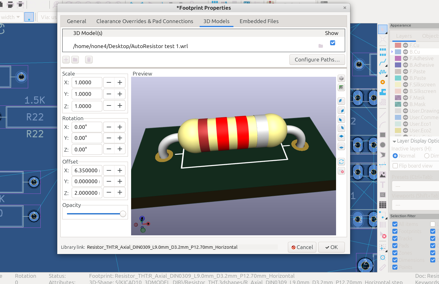
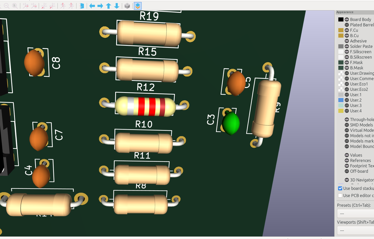
and here is the output in Kicad: