
3D part design with Inkscape and OpenSCAD #77: More with the shape builder tool and checking dimensions before 3d printing.
In the last post I used the shape builder tool in Inkscape to do some basic addition and subtraction of objects, in this post I'm going to use it to add multiple cut outs to a new design.
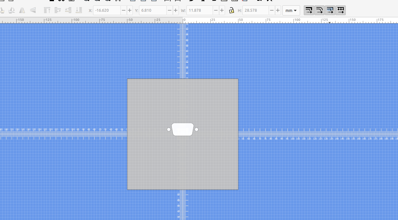
Here is a plate with a Db9 connector and I only want the outline of the connector:
I'm going to open it in the shape builder and only add the parts I want to save:
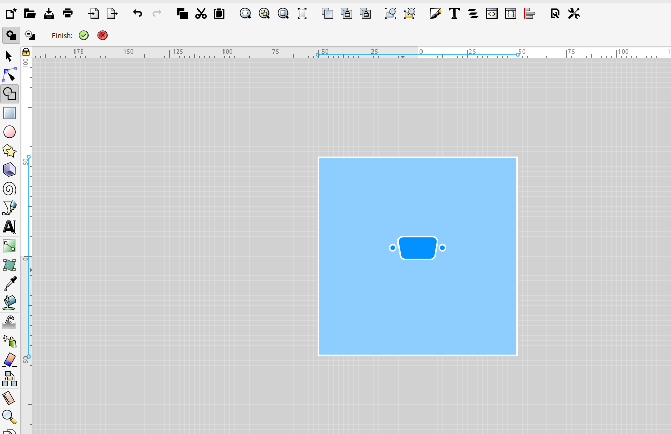
Then I can group them, move them to the top and make them a solid color:
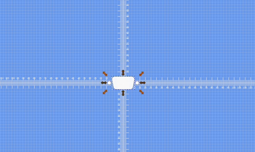
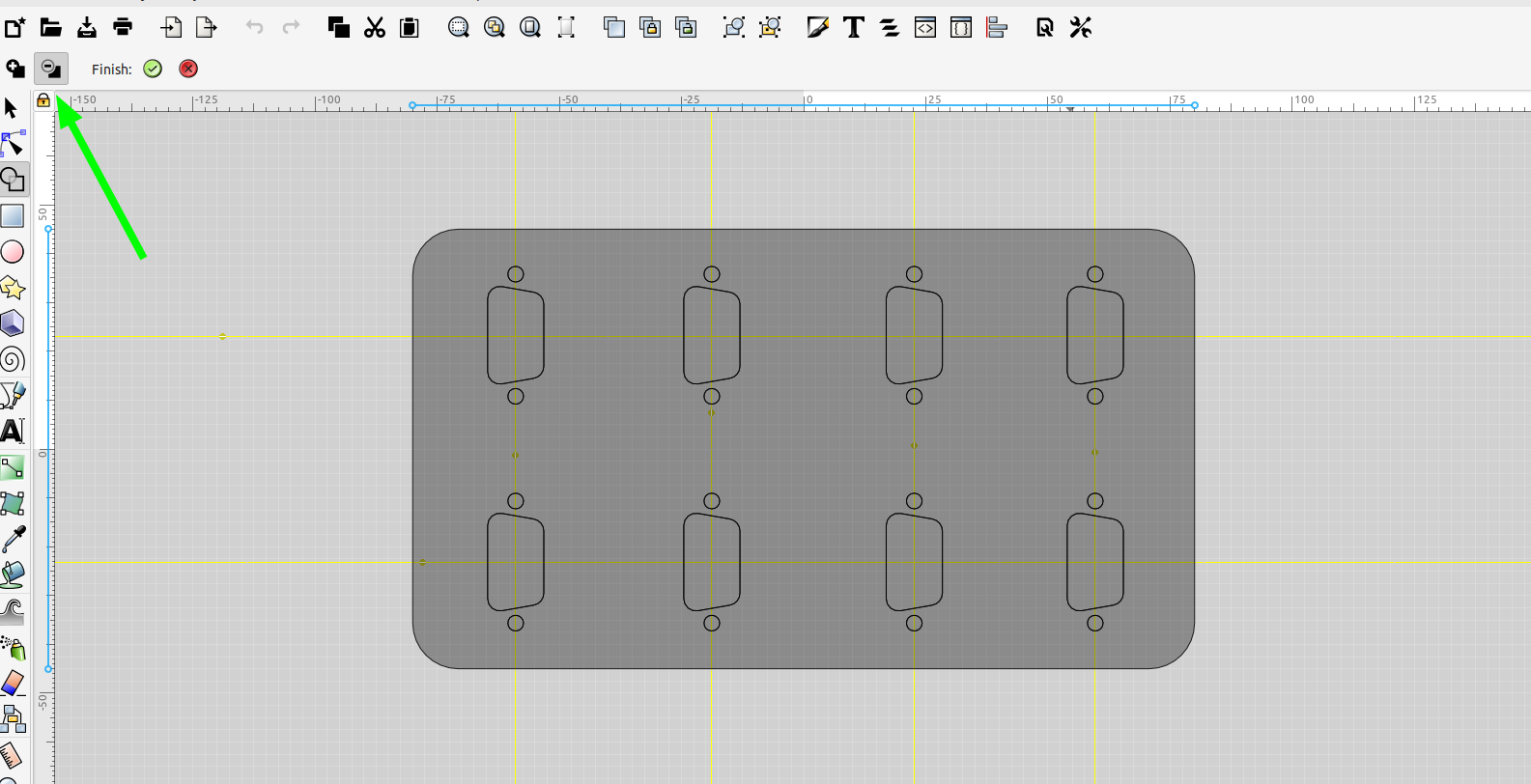
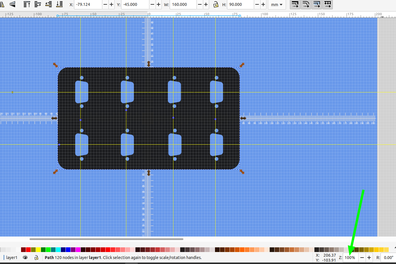
Now I can use this to make multiple copies and cut them out of a new plate:
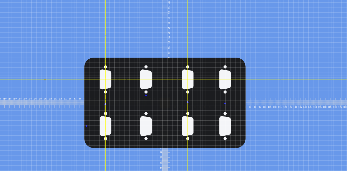
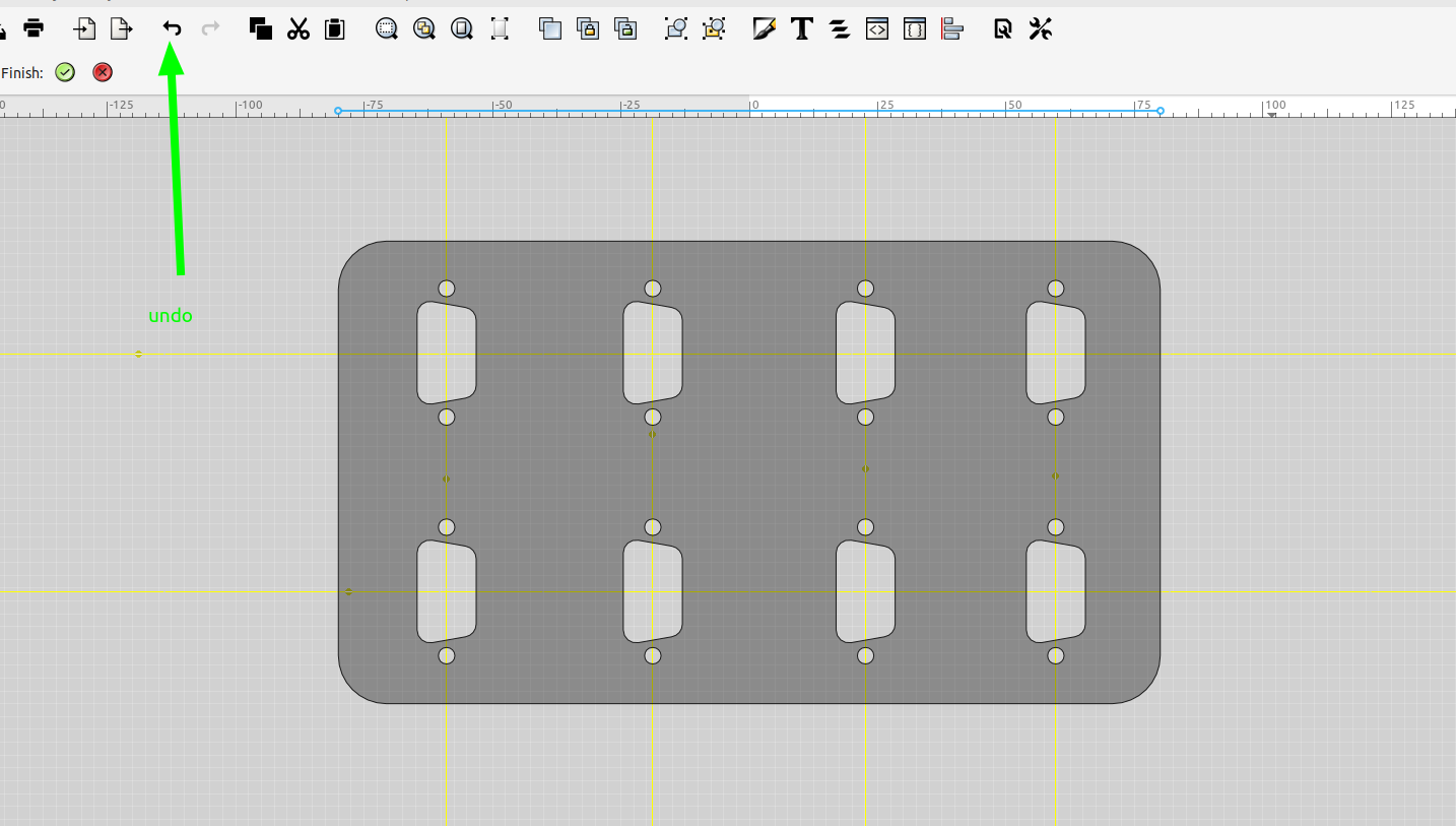
If you delete the wrong object just click undo:
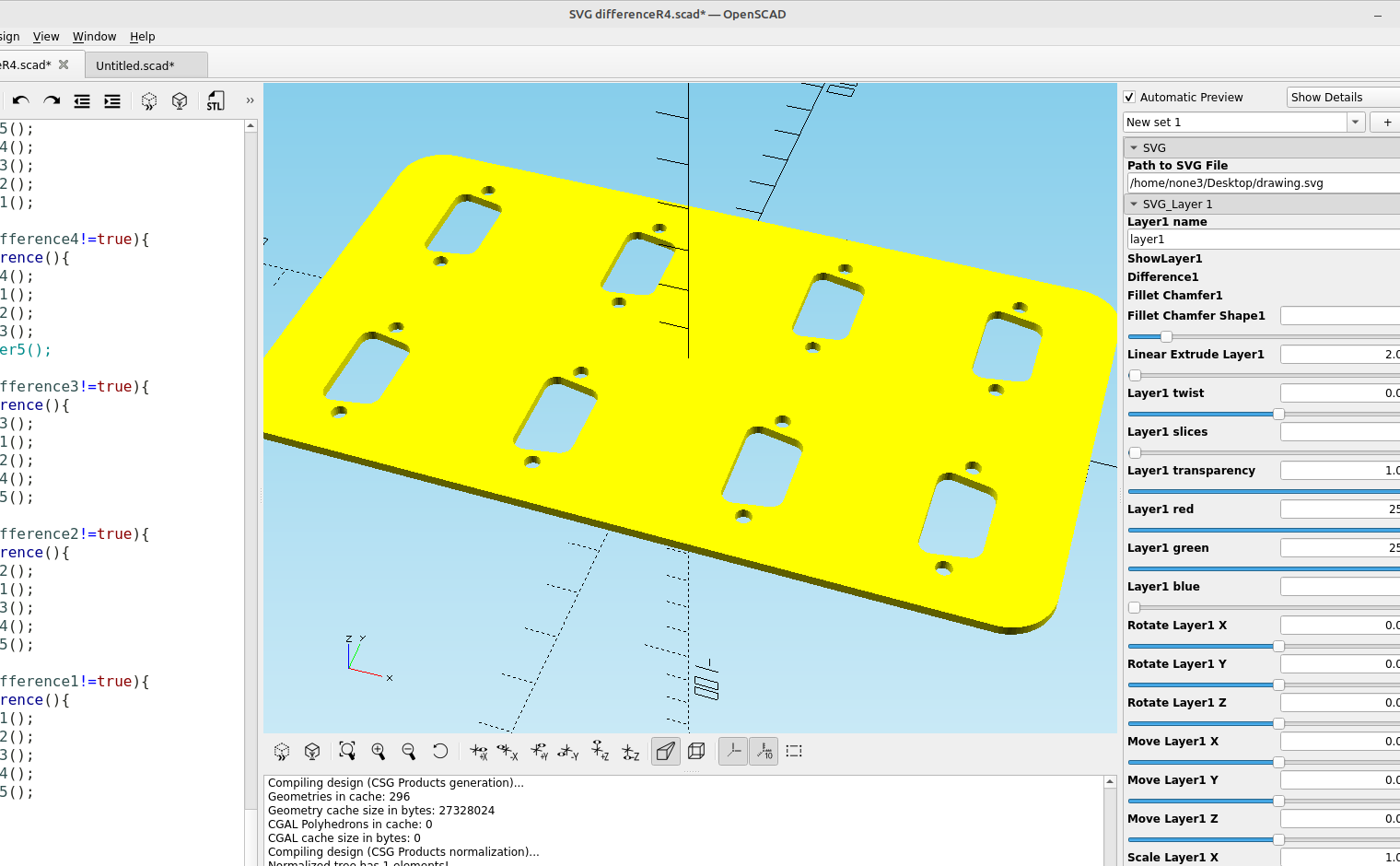
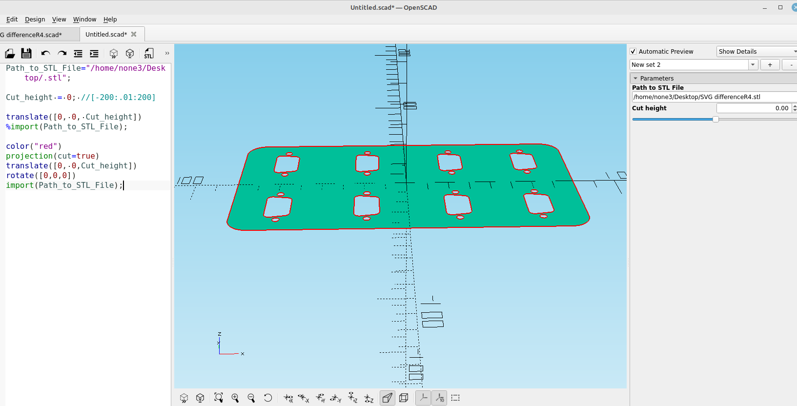
When I have them the way I want I can save the file and import it into OpenSCAD:

Before I print this I want to check to make sure the objects I just made are the right size for the connectors. In post #41 I made a module to reverse engineer an stl file so I'm going to use that to check the dimensions:
 Bob
Bob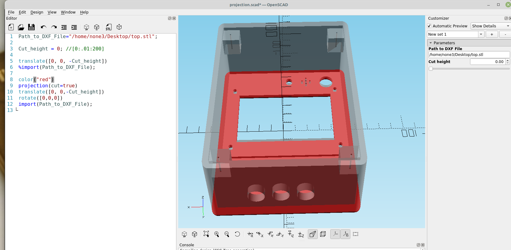
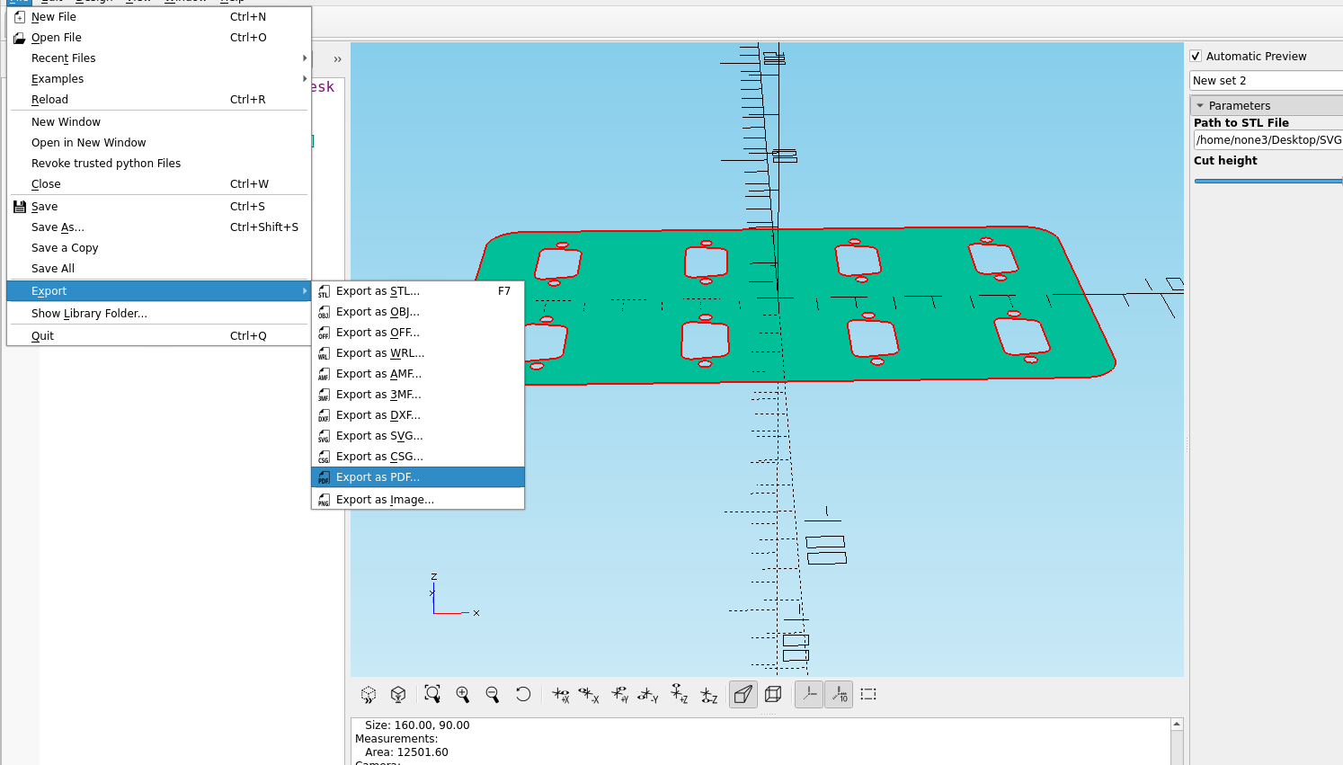
I can save it to pdf and print it out on paper before I 3d print it:
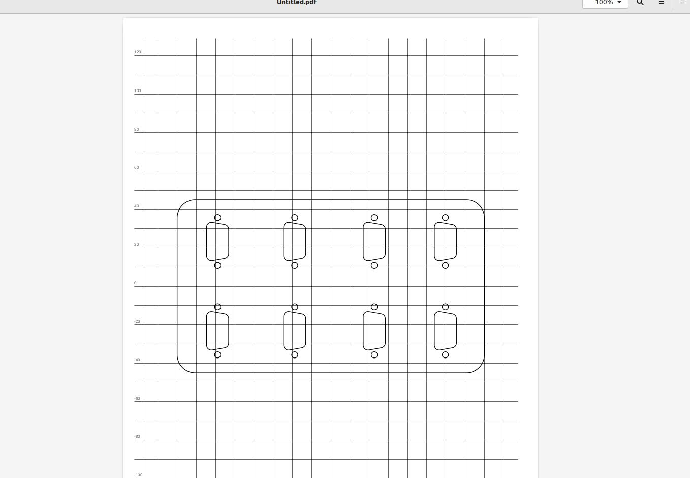
You probably want about.2 mm around each object to account for the line thickness of the plastic your printer will put down, if your printer is properly calibrated it will usually be right on the money.
Of course there is a way to check the size without printing it out on paper, in Inkscape goto Edit>Preferences> Interface and set the zoom correction factor with a ruler or calipers:
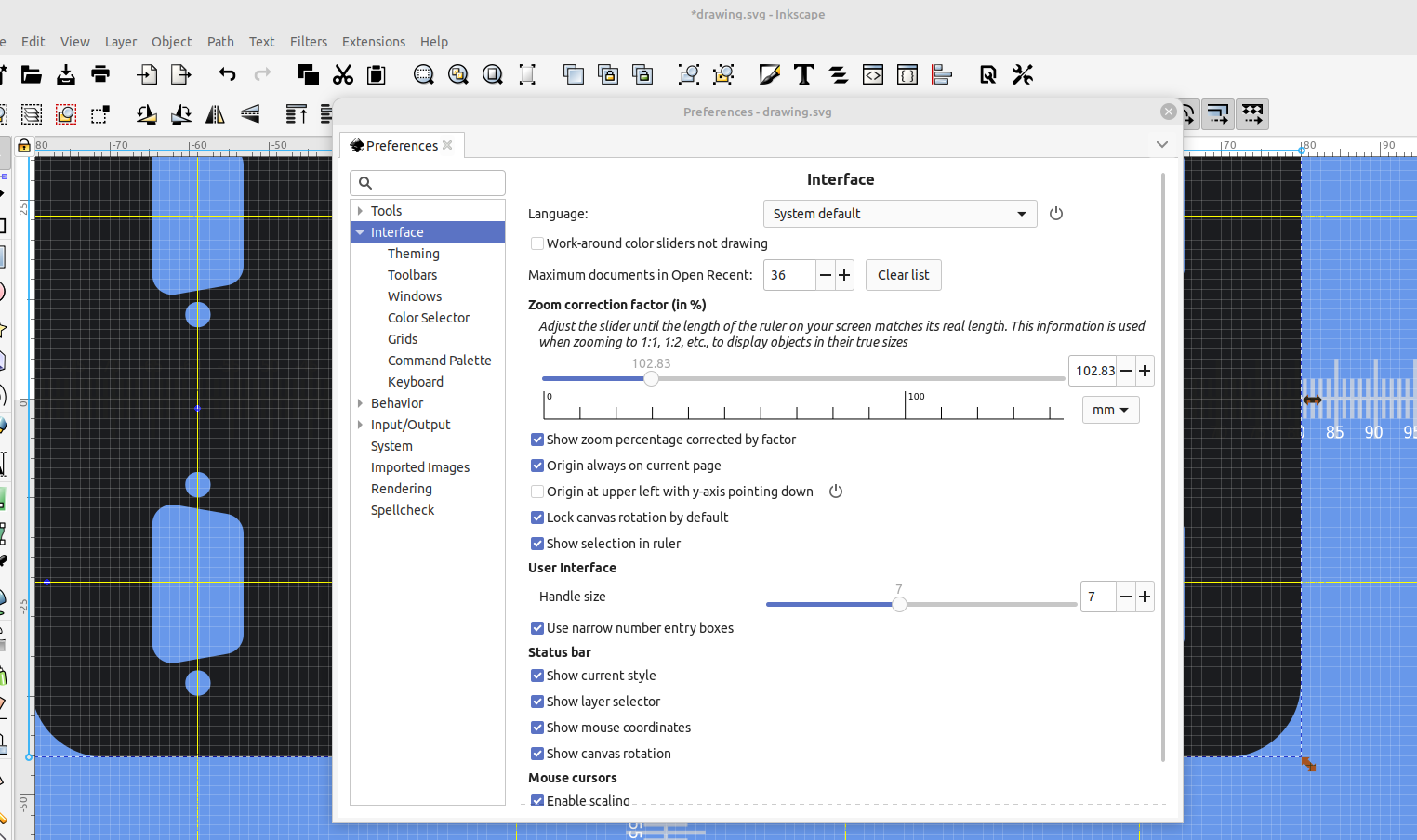
Now when the zoom is at 100 percent you can hold your object against the screen and verify the size:
Once you have a system down it's pretty easy to design cut outs that are the perfect size every time.