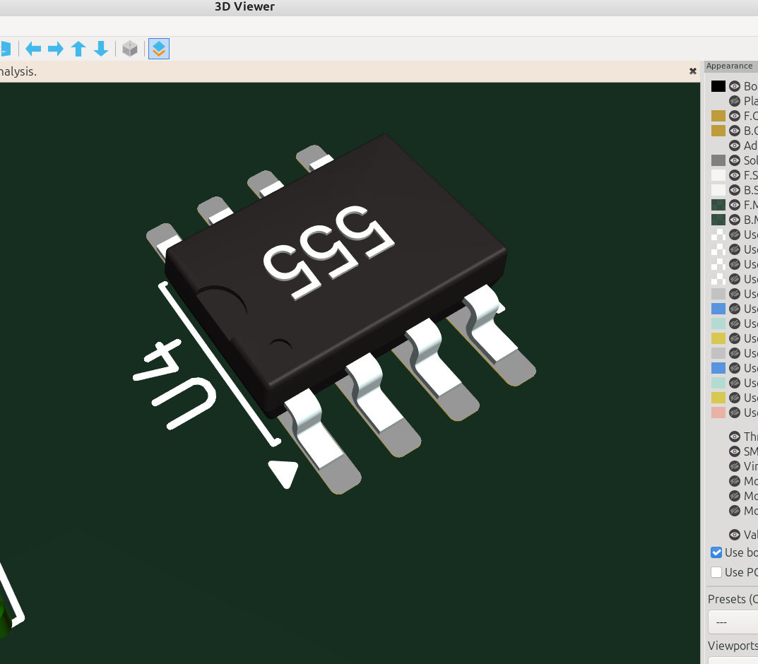
3D part design with OpenSCAD #155: An SMT model generator and customizer for Kicad.
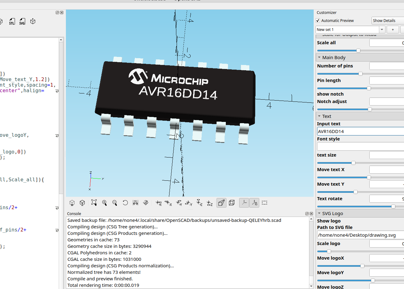
Since I had already made the other customizer for inline DIP chips it was pretty easy to make one for SMT components by just changing the leads a bit.
here is the code:
//

//SMT Dual Inline Package IC customizer Version 3 for Kicad  by InfinityPlays.com//
//License- Public Domain

/*[Scale for Output to Kicad]*/
Scale_all=1;//[.001:.001:1]

/*[Main Body]*/
Number_of_pins=8;//[4:2:28]
show_notch=false;
Notch_adjust=.1;//[-4:.01:4]

/*[Text]*/
Input_text="U1";
Font_name="";
text_size=2;//[.1:.1:3]
Move_text_X=0;//[-12:.01:12]
Move_text_Y=0;//[-2:.01:2]
Text_rotate=90;//[-180:.01:180]

/*[SVG Logo]*/
Show_logo=false;
Path_to_SVG_file="";
Scale_logo=1;//[.001:.001:1]
Move_logoX=0;//[-10:.01:10]
Move_logoY=0;//[-10:.01:10]
Move_logoZ=0;//[-10:.01:10]

module body(){
 translate([0,-.25,0])
minkowski(){
 linear_extrude(1,scale=.90)
 square([2,Number_of_pins/2.5],center=true);
 mirror([0,0,1])
 linear_extrude(1,scale=.92)
 square([3.8,Number_of_pins/1.2],center=true);
 sphere(.2,$fn=60);
}

}

module pins(){
 $fn=100;
 color("azure")
  translate([0,1.5,0])
for(i=[-Number_of_pins/4:1:Number_of_pins/4-1])
  translate([0,i*2.54,0])
  rotate([90,0,0]){
  rotate([0,0,90])
  translate([-.9,-3.81,-.1])
  cube([.5,.25,1]);
  translate([3.36,0.05,-.1])
  rotate([0, 0, 180])
  cube([2,.25,1]);
  rotate([0,0,0])
  translate([4,-1.35,-.1])
  cube([1,.25,1]);
  translate([3.36,-.4,-.1])
  rotate_extrude(angle = 90)
  translate([.2,0,0])
  square([.25,1]);
  translate([4.01,-.9,-.1])
  rotate([0,0,180])
  rotate_extrude(angle = 90)
  translate([.2,0,0])
  square([.25,1]);
}}

module Text(){
  color("white")
  linear_extrude(1.3)
  rotate([0,0,Text_rotate])
  translate([Move_text_X,Move_text_Y,1.2])
  text(Input_text,font=Font_name,spacing=1,
  size=text_size,valign="center",halign="center",$fn=50);
}

 module Logo(){
  if(Show_logo)
  color("white")
  rotate([0,0,90])
  translate([Move_logoX,Move_logoY,Move_logoZ])
  linear_extrude(.65)
  scale([Scale_logo,Scale_logo,.1])
  import(Path_to_SVG_file);
}

 translate([0,0,0]){
 scale([Scale_all,Scale_all,Scale_all]){
 difference(){
 color("#242020")
 body();
if(show_notch){
 translate([0,Number_of_pins/2+Notch_adjust,1])
 #color("#242020")
 cylinder(.5,1,1,$fn=30);
 translate([-2.1,Number_of_pins/2+Notch_adjust-1,1])
 #color("#242020")
 cylinder(.5,.4,.3,$fn=30);
}}
 mirror([1,0,0])
 pins();
 pins();
 Text();
 Logo();
}}
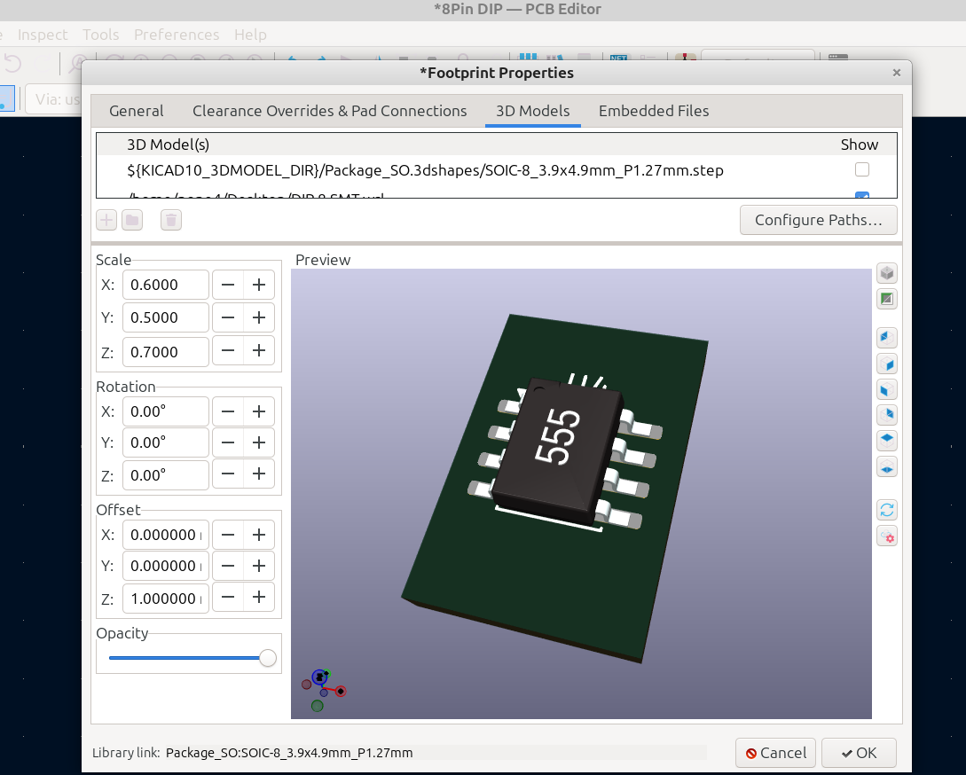
I had to do some adjusting to get it just right, luckily Kicad has an excellent and easy way to do this upon import:
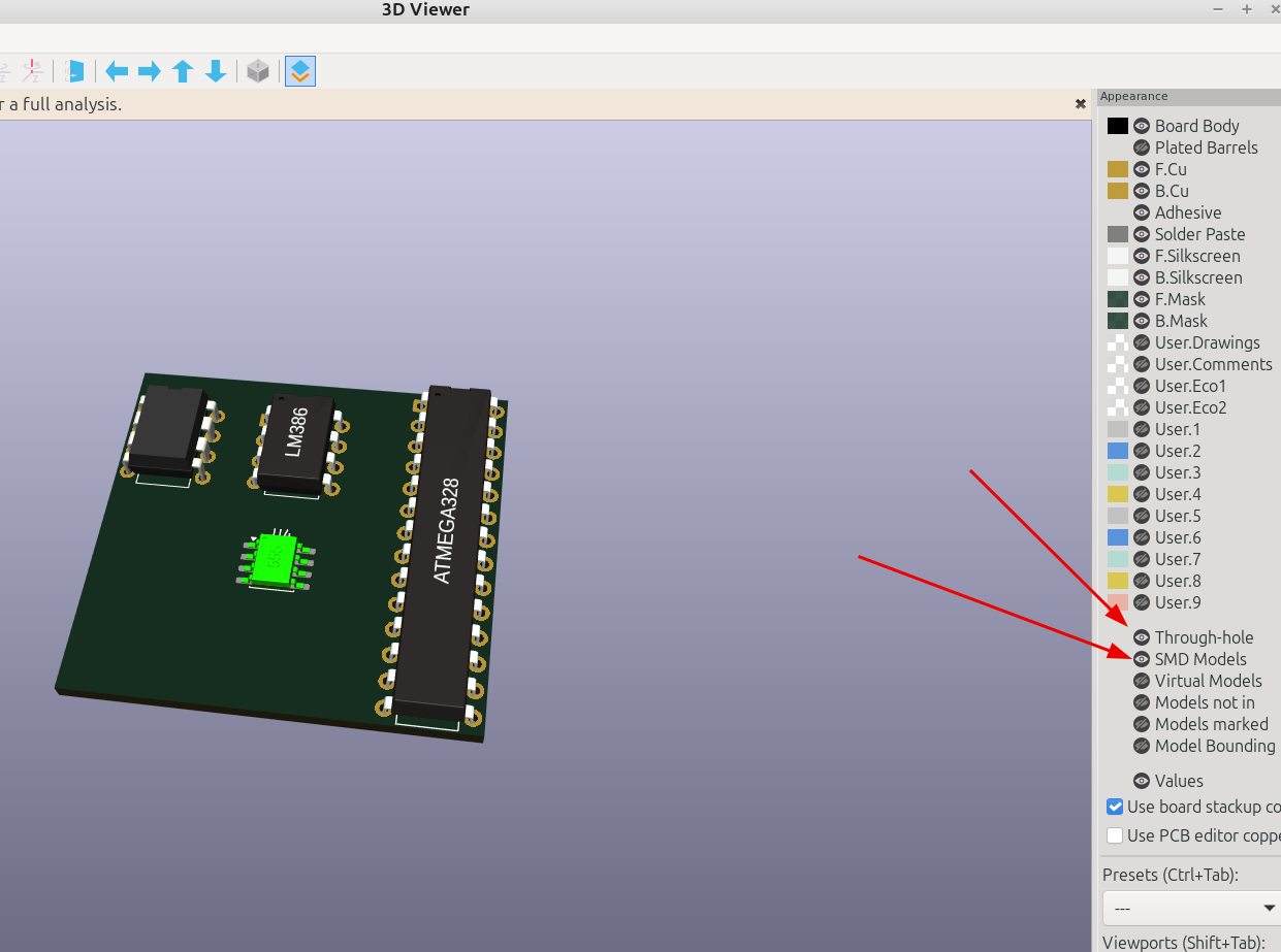
Here I made a test board to see how things look:
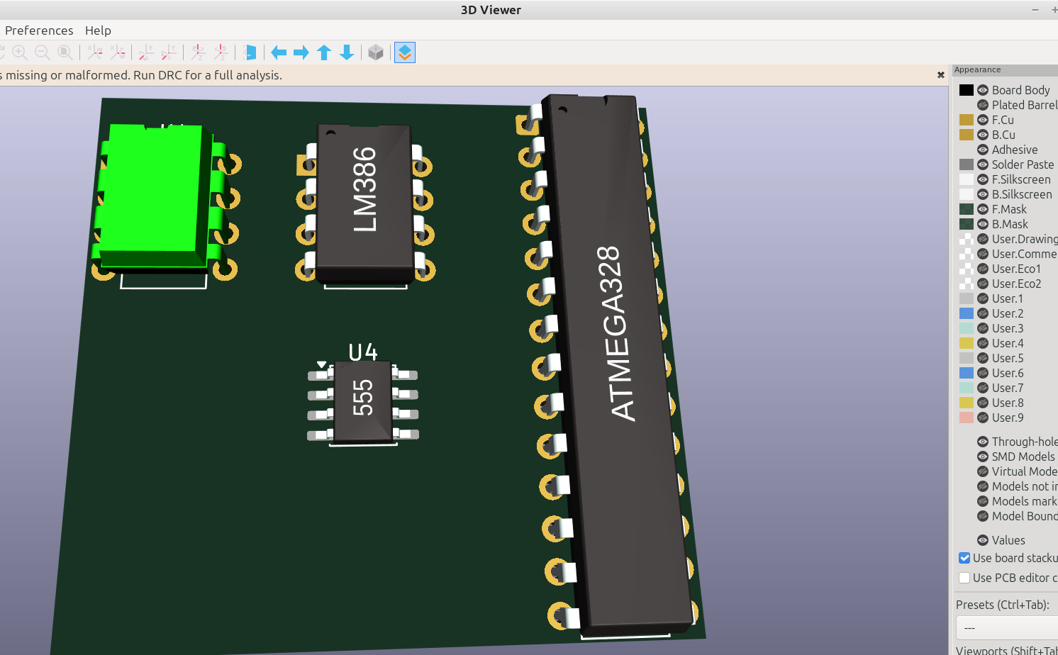
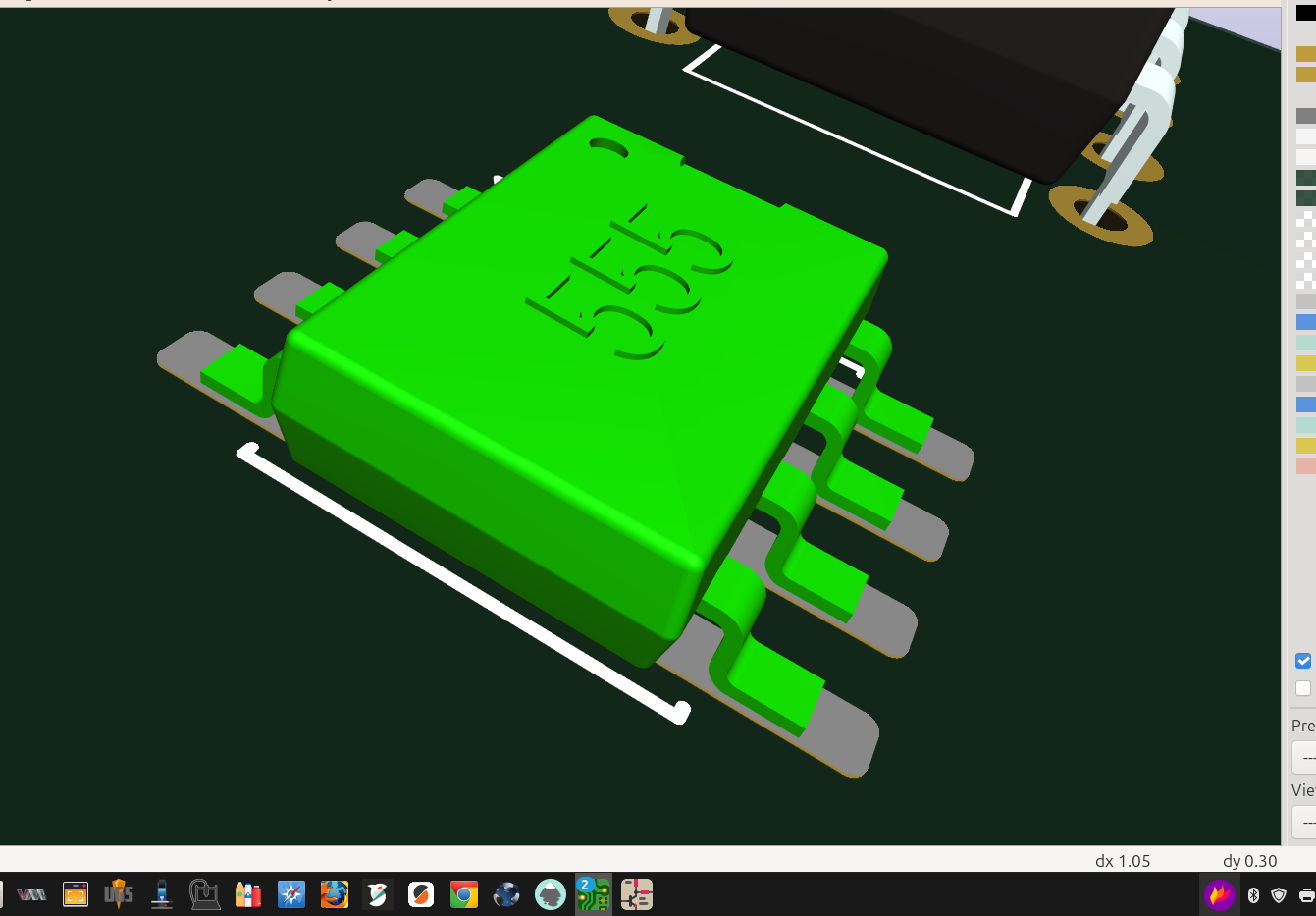
If you don't see any of the models in the 3D viewer make sure the visibility is turned on: