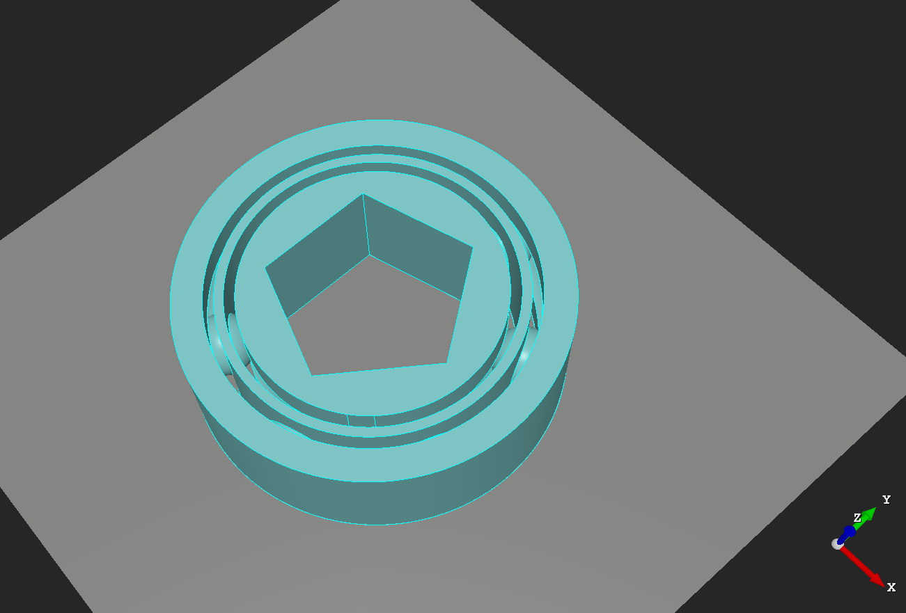
I needed to design a bearing and since I already had most of the code written for other modules I recycled the code from them to make a customizable bearing module.
Note: I highly recommend using the development version of openscad I mentioned in post #31, due to the multiple difference commands used for this it takes a while to render on the stable version, but only a few seconds to render with the development version.
Also this is a work in progress and I am still working on the taper function, but as is it does produce usable results very quickly.
Here is the code:
 /*[Ball]*/
   Show_ball = true;
   Ball_size = 7; //[1:.01:100]
   Ball_clearance = 0; //[0:.1:100]
   Ball_verticle_spacing = 20; //[1:.1:200]
   Ball_horizontal_spacing = 51.42; //[1:.01:200]
   Move_ball_horizontal = 20; //[0:.01:100]
   Move_ball_X = 0; //[-200:.1:200]
   Move_ball_Y = 0; //[-200:.1:200]
   Move_ball_Z = 0; //[-200:.1:200]
/*[Groove]*/
   Show_Groove = true;
/*[Outer_Race]*/
   Show_race1 = true;
   Race1_spacing = 0; //[0:.01:20]
   Race1_inside_diameter = 42.5; //[0:.1:200]
   Race1_outside_diameter= 49.5; //[0:.1:200]
   Race1_height = 0 ; //[-18.75:.01:100]
   Race1_inside_shape = 200; //[0:1:200]
   Race1_outside_shape = 200; //[0:1:200]
   Rotate_Race1_X = 0; //[0:.1:360]
   Rotate_Race1_Y= 0; //[0:.1:360]
   Rotate_Race1_Z = 0; //[0:.1:360]
   Move_race1_X = 0; //[0:.1:200]
   Move_race1_Y = 0; //[0:.1:200]
   Move_race1_Z = 0; //[0:.1:200]
 /*[Inner_Race]*/
   Show_race2 = true;
   Race2_spacing = 0; //[0:.01:20]
   Race2_inside_diameter = 30; //[0:.1:200]
   Race2_outside_diameter= 38; //[0:.1:200]
   Race2_height = 0 ; //[-18.75:.01:100]
   Race2_inside_shape = 200; //[0:1:200]
   Race2_outside_shape = 200; //[0:1:200]
   Rotate_Race2_X = 0; //[0:.1:360]
   Rotate_Race2_Y= 0; //[0:.1:360]
   Rotate_Race2_Z = 0; //[0:.1:360]
   Move_race2_X = 0; //[0:.1:200]
   Move_race2_Y = 0; //[0:.1:200]
   Move_race2_Z = 0; //[0:.1:200]
/*[Cage]*/
   Show_Cage = true;
   Cage_outside_diameter = 41; //[0:.01:200]
   Cage_inside_diameter = 39.5; //[.1:.01:200]
   Cage_height = 0 ; //[-18.75:.01:100]
   Inside_shape = 200; //[3:1:200]
   Outside_shape = 200; //[3:1:200]
   Rotate_Cage_X = 0; //[0:.1:360]
   Rotate_Cage_Y = 0; //[0:.1:360]
   Rotate_Cage_Z = 0; //[0:.1:360]
   Move_cage_X = 0; //[0:.1:200]
   Move_cage_Y = 0; //[0:.1:200]
   Move_cage_Z = 0; //[0:.1:200]
/*[Rows and Columns]*/
   Columns = 1; //[1:20]
   Rows = 7; //[1:360]
/*[Taper]*/
   Taper = 1; //[1:1:20]
/*[Rotate]*/
   Rotate_All_X = 0; //[0:.1:360]
   Rotate_All_Y = 0; //[0:.1:360]
   Rotate_All_Z = 0; //[0:.1:360]

module Ball(){
for(v=[1:Columns]){
    rotate([Rotate_All_X,Rotate_All_Y,Rotate_All_Z])
    translate([Move_ball_X,Move_ball_Y,Move_ball_Z-9])
    translate([0,0,v*Ball_verticle_spacing-.5])
for(h=[1:Rows])
   rotate([0,0,h*Ball_horizontal_spacing])
   translate([0,-Move_ball_horizontal,0])
   sphere(Ball_size/2,$fn=100);
 }}

module BallClearance(){
 for(v=[1:Columns]){
    rotate([Rotate_All_X,Rotate_All_Y,Rotate_All_Z])
    translate([Move_ball_X,Move_ball_Y,Move_ball_Z-9])
    translate([0,0,v*Ball_verticle_spacing-.5])
 for(h=[1:Rows])
    rotate([0,0,h*Ball_horizontal_spacing])
    translate([0,-Move_ball_horizontal,0])
    sphere(Ball_size/2+ Ball_clearance,$fn=100);
 }}

module groove(){
if(Show_Groove)
 for(g=[1:Columns]){
    rotate([Rotate_All_X,Rotate_All_Y,Rotate_All_Z])
    translate([Move_ball_X,Move_ball_Y,Move_ball_Z-9])
    translate([0,0,g*Ball_verticle_spacing-.5])
    rotate_extrude(convexity = 10,$fn=100)
    translate([Cage_outside_diameter/2, 0, 0])
    circle(r = Ball_size/2+.5);
}}

module Cage(){
 if (Show_Cage)
   translate([Move_cage_X,Move_cage_Y,Move_cage_Z])
   rotate([Rotate_All_X,Rotate_All_Y,Rotate_All_Z])
   rotate([Rotate_Cage_X,Rotate_Cage_Y,Rotate_Cage_Z])
   linear_extrude(Ball_verticle_spacing*Columns+Cage_height,scale=Taper,convexity=11)
difference(){
    circle(Cage_outside_diameter/2,$fn=Outside_shape);
    circle(Cage_inside_diameter/2,$fn=Inside_shape);
}}

module Race1(){
     if (Show_race1)
 translate([Move_race1_X,Move_race1_Y,Move_race1_Z])
 rotate([Rotate_All_X,Rotate_All_Y,Rotate_All_Z])
 rotate([Rotate_Race1_X,Rotate_Race1_Y,Rotate_Race1_Z])
 linear_extrude(Ball_verticle_spacing*Columns+Race1_height,scale=Taper,convexity=11)
difference(){
    circle(Race1_outside_diameter/2+Race1_spacing,$fn=Race1_outside_shape);
    circle(Race1_inside_diameter/2+Race1_spacing,$fn=Race1_inside_shape);
}}

module Race2(){
     if (Show_race2)
 translate([Move_race2_X,Move_race2_Y,Move_race2_Z])
 rotate([Rotate_All_X,Rotate_All_Y,Rotate_All_Z])
 rotate([Rotate_Race2_X,Rotate_Race2_Y,Rotate_Race2_Z])
 linear_extrude(Ball_verticle_spacing*Columns+Race2_height,scale=Taper,convexity=11)
difference(){
    circle(Race2_outside_diameter/2+Race2_spacing,$fn=Race2_outside_shape);
    circle(Race2_inside_diameter/2+Race2_spacing,$fn=Race2_inside_shape);
}}

module Show_ball(){
if (Show_ball)
Ball();
}

difference(){
Race1();
Ball();
groove();
//BallClearance();//for captive ball uncomment and disable groove
}
difference(){
Race2();
Ball();
groove();
//BallClearance();//for captive ball uncomment and disable groove
}

difference(){
Cage();
Ball();
BallClearance();
}

Show_ball();
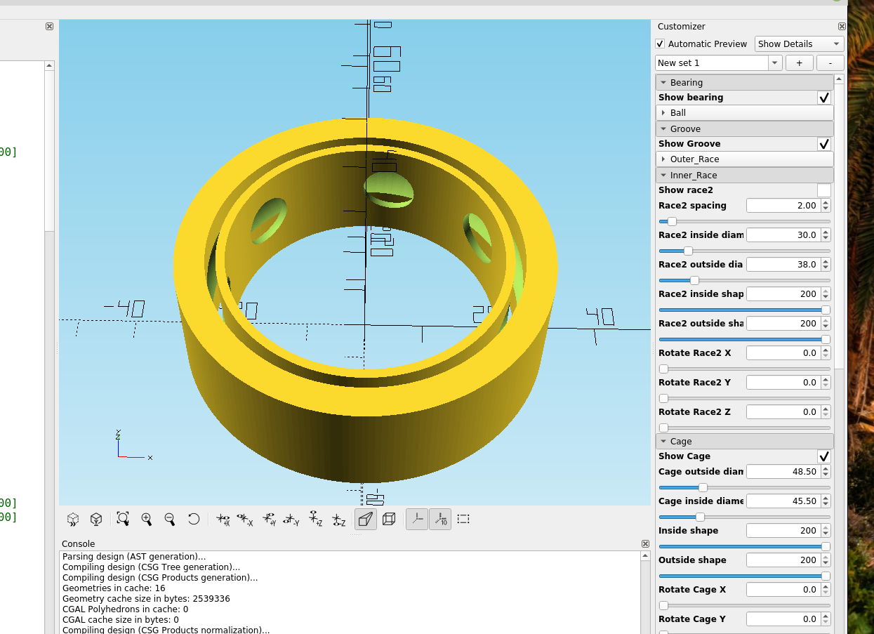
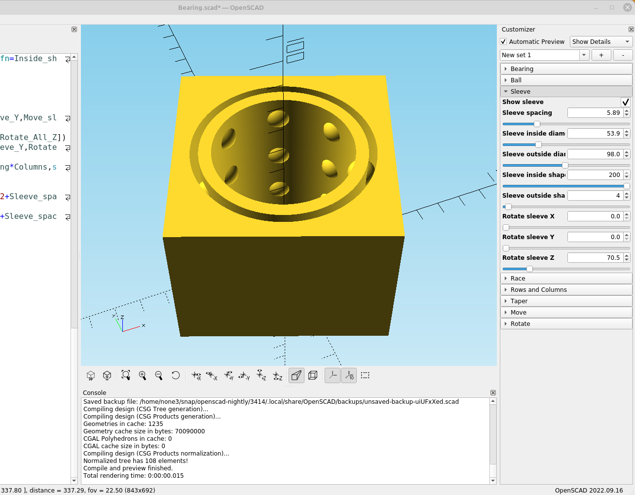
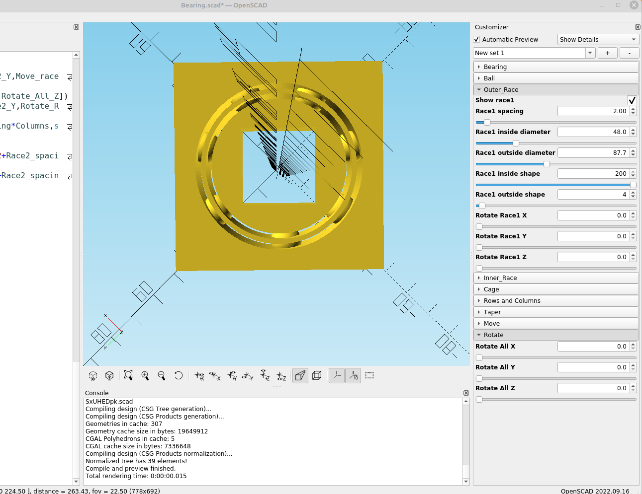
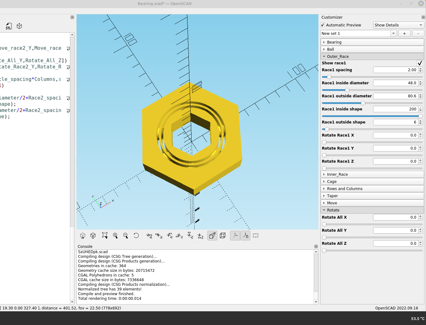
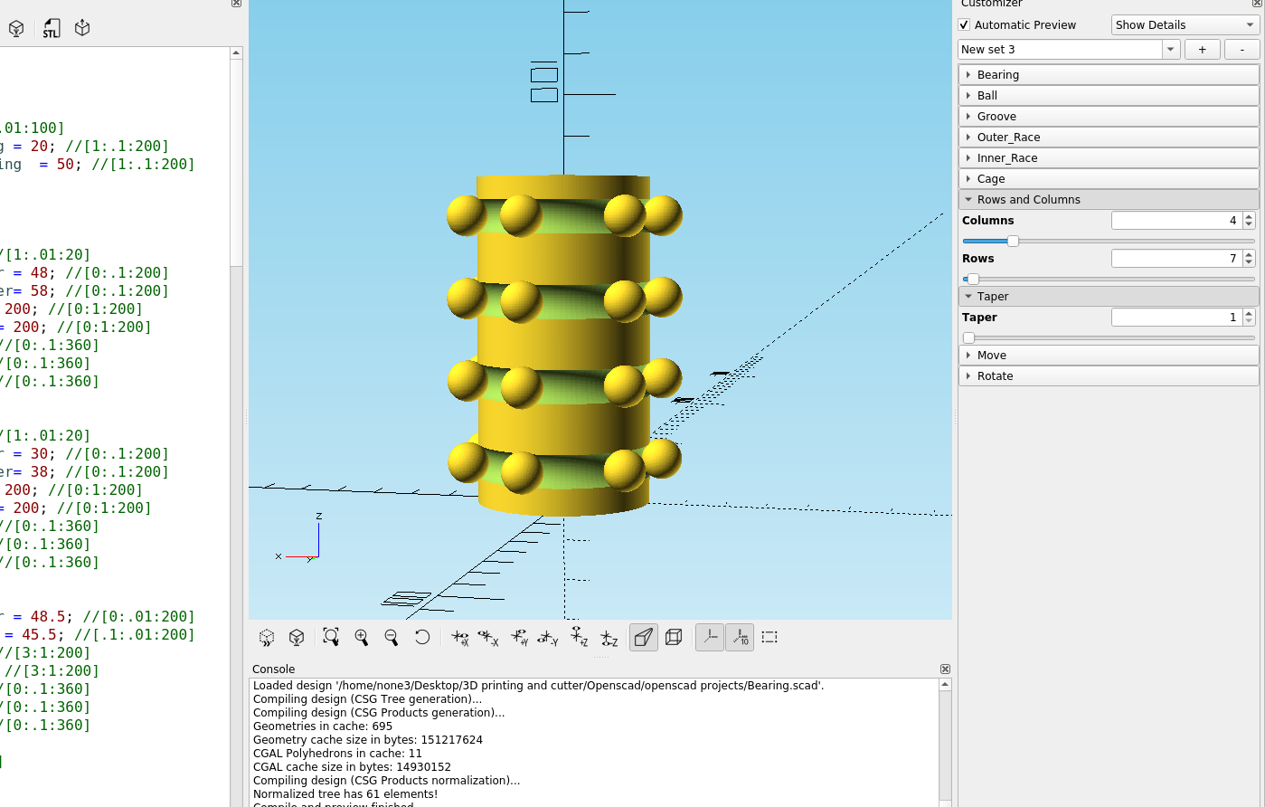
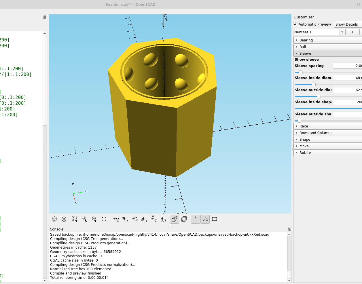
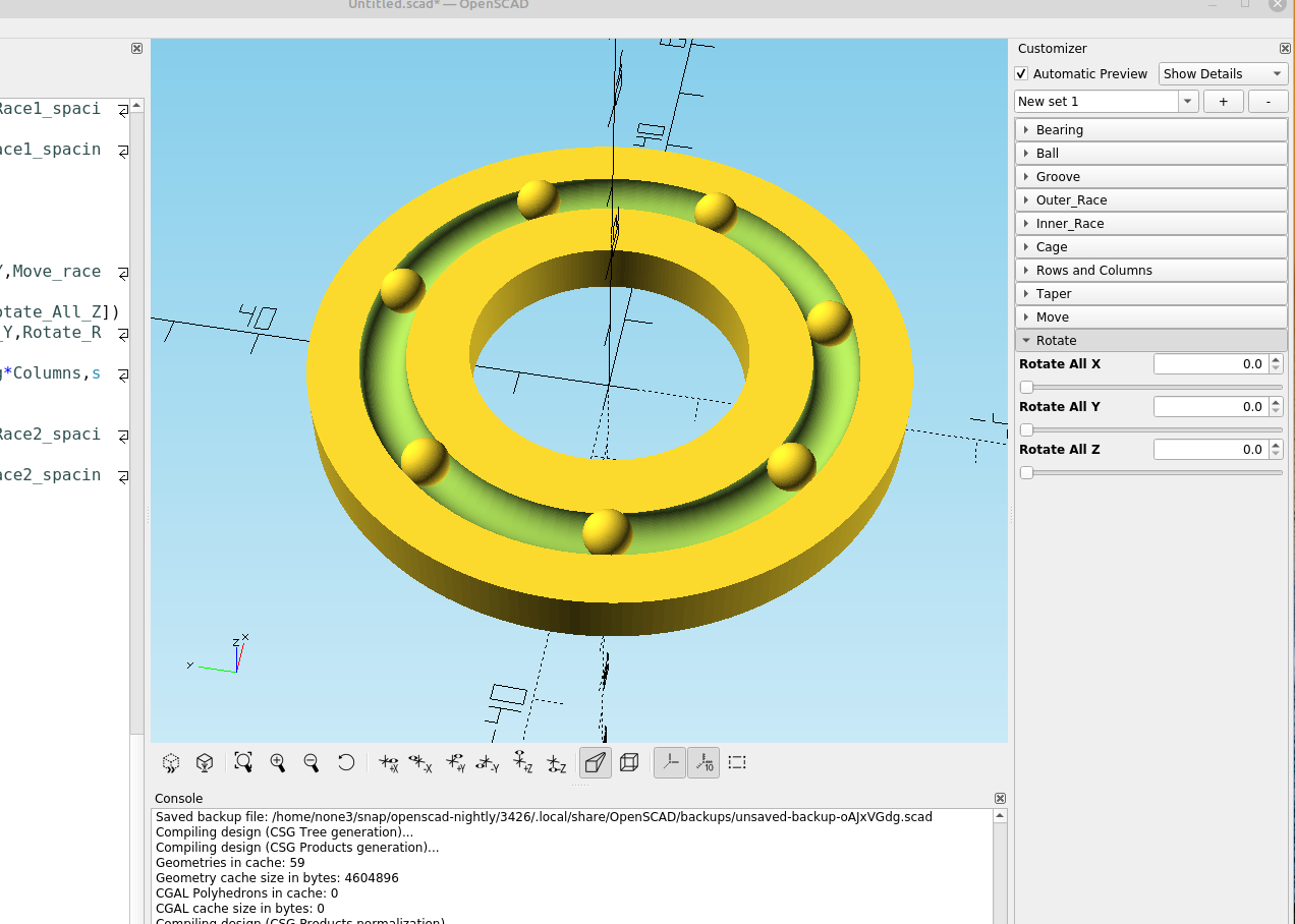
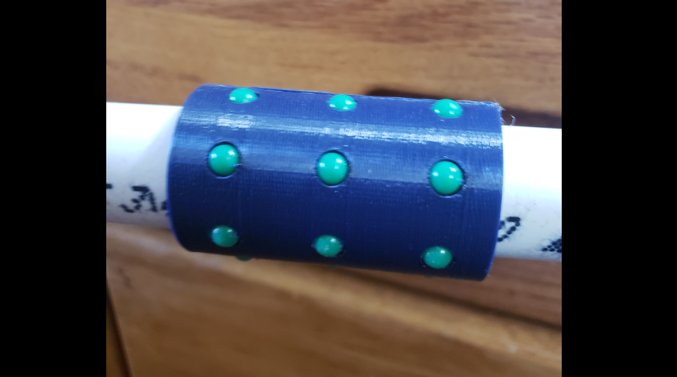
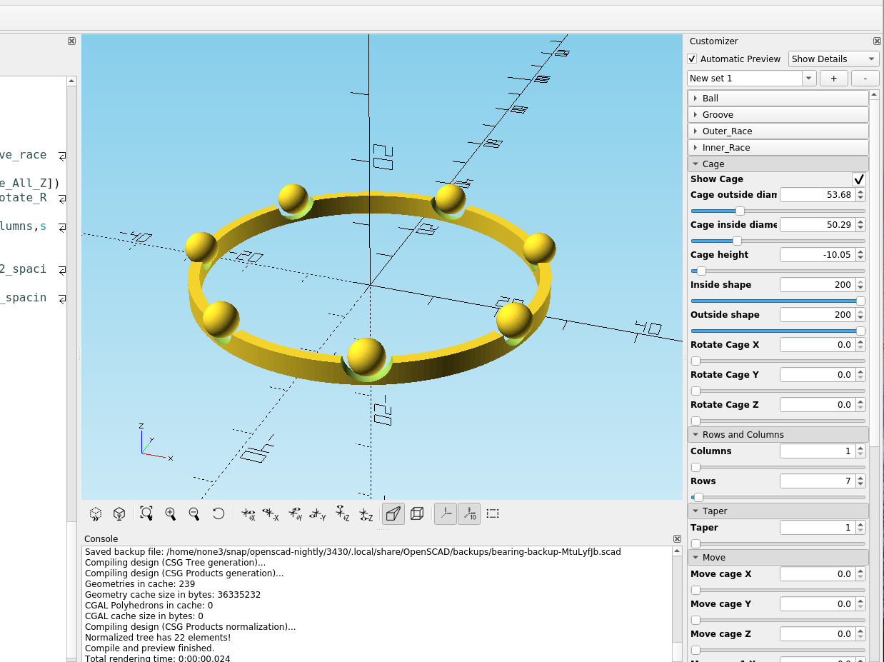
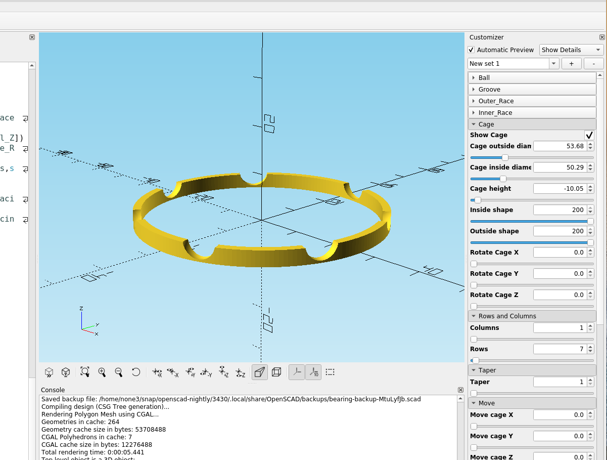
And here are some different results from tweaking the variables:
Note: It works well to make your ball size .2 mm bigger than the actual size of ball you are going to use, that gives it about .1 clearance around the ball. Just un-check show ball to print the bearing with holes for metal or plastic BBs or marbles.
To do:
Add an additional ring so I can add a wire raceway to the races, finish the taper stuff.
Update:
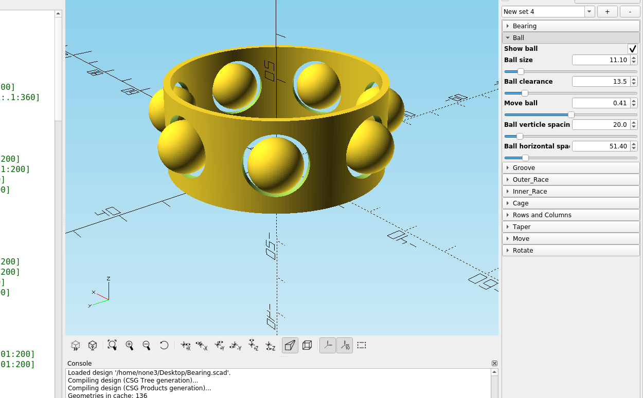
I fixed the size problem with the ball size, made the spacing setting for the races so it will adjust to zero, made a .5 gap for the groove and I added a ball clearance module so the bearing could be a print in place bearing. initially I had planned on using only steel or ceramic balls but it will be handy to be able to make a print in place bearing. I didn't catch the errors until I made some test prints, and with this many variables that you can adjust it doesn't take much to make things go off track, but it is still a very fast way to design a custom bearing.
Here is a slicer to cut the different components in half for the longer bearings:
/*[Slice]*/
Width = 100; //[0:.1:200]
Height = 100; //[0:.1:200]
Thickness = 0.5; //[0:.1:100]
Rotate_x = 0; //[-360:.01:360]
Rotate_y = 0; //[-360:.01:360]
Rotate_z = 0; //[-360:.01:360]
Move_x = 0; //[-360:.01:360]
Move_y = 0; //[-360:.01:360]
Move_z = 0; //[-360:.01:360]


difference(){
import("/home/none3/Desktop/tall cage.stl",convexity=11);
translate([0,0,Height/2])
rotate([Rotate_x,Rotate_y,Rotate_z])
translate([Move_x,Move_y,Move_z])
cube([Width,Thickness,Height],center = true);
}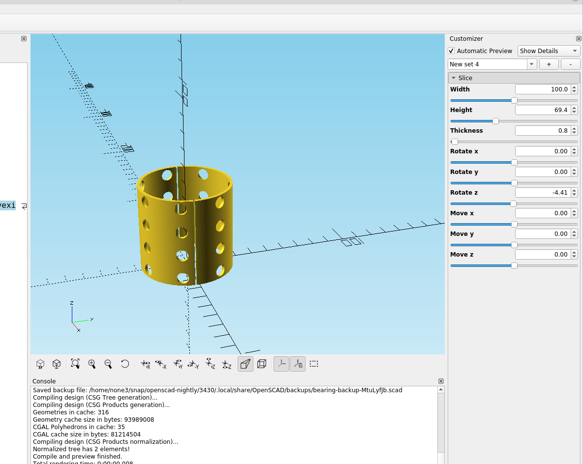
I use the extruder tip to weld the two halves back together.
