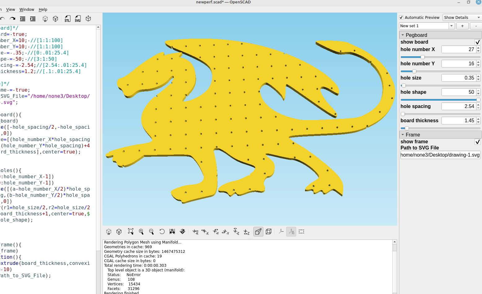
After I made the pegboard module in post # 61 I decided to make a way to cut it out to any shape I wanted so I could make some cool looking pegboards instead of the plain old square ones.
Here is the updated code:
/*[Pegboard]*/
show_board= true;
hole_number_X=10; //[1:1:400]
hole_number_Y=10; //[1:1:400]
hole_size = .35; //[0:.01:25.4]
hole_shape = 50; //[3:1:50]
hole_spacing = 2.54;//[2.54:.01:25.4]
board_thickness=1.2;//[.1:.01:25.4]

/*[Frame]*/
show_frame = true;
Path_to_SVG_File="/home/none3/Desktop/File.svg";

module board(){
if(show_board)
translate([-hole_spacing/2,-hole_spacing/2,0])
cube(size=[(hole_number_X*hole_spacing)+4,(hole_number_Y*hole_spacing)+4,board_thickness],center=true);
}

module holes(){
for(a=[0:hole_number_X-1])
for(b=[0:hole_number_Y-1])
translate([(a-hole_number_X/2)*hole_spacing,(b-hole_number_Y/2)*hole_spacing,0])
cylinder(r1=hole_size/2,r2=hole_size/2,h=board_thickness+1,
center=true,$fn=hole_shape);
}


module frame(){
if(show_frame)
intersection(){
linear_extrude(board_thickness,convexity = 10)
import(Path_to_SVG_File);
board();
}
else{
board();
}}

difference(){
frame();
holes();
}
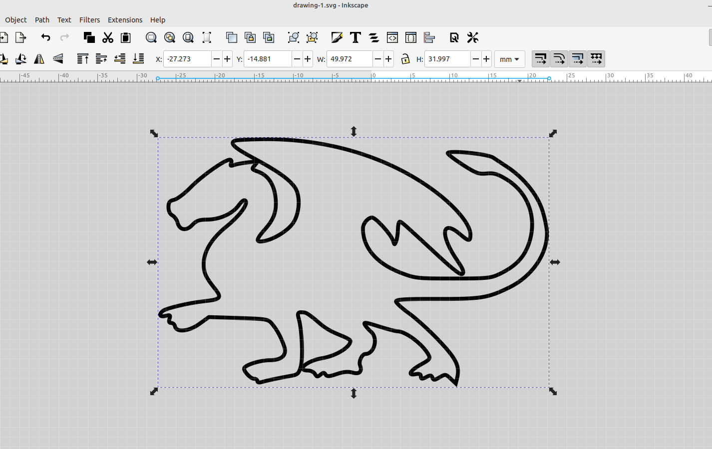
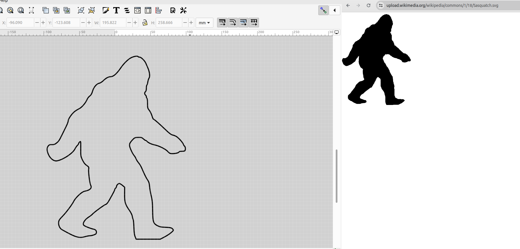
Now I can take a screenshot of anything I can see, import the image into Inkscape and trace it to use it as an outline for the pegboard/perfboard.
I used the same method I used in post # 89 to make an outline of the traced image, and then made a frame module for OpenSCAD:
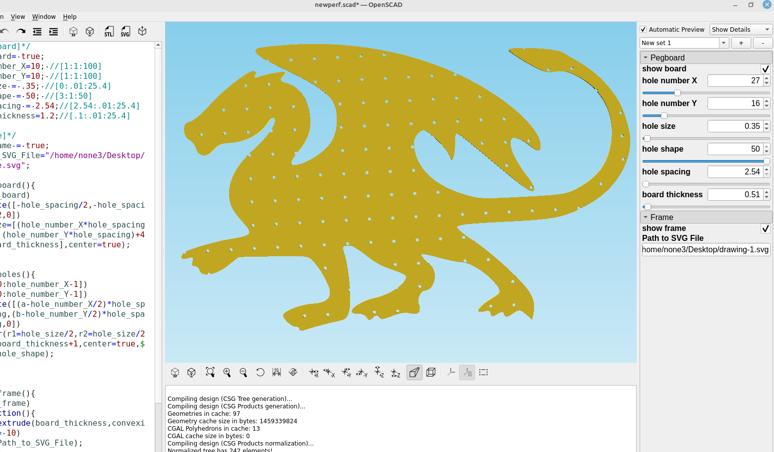

It takes a while to render even using manifold if it is the full size of my print bed, probably because of all the holes, some experimentation will need to be done to see if that can be fixed.
