
3D part design with OpenSCAD #121: Electronics enclosure helper.
Lining up the holes for different ports on an enclosure can be tedious, here is a helper program made with OpenSCAD that helps to align the holes,make them a bit bigger if needed and make them fit nicely.
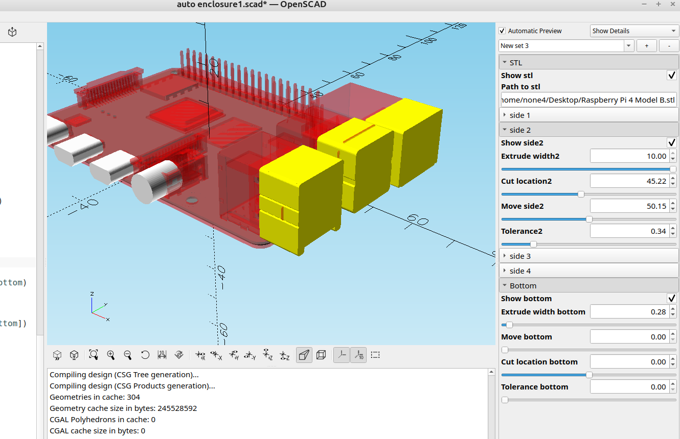
The code takes a slice from the different sides of an existing stl model and allows you to move the cut location and make them longer to extend through the sides of the case.
Here is the code:
//

/*[STL]*/
Show_stl=false;
Path_to_stl=("");

/*[side 1]*/
Show_side1=false;
Extrude_width1=1;//[.01:.01:30]
Cut_location1=0;//[0:.01:100]
Move_side1=0;//[0:.01:100]
Tolerance1=0;//[0:.01:1]

/*[side 2]*/
Show_side2=false;
Extrude_width2=1;//[.01:.01:10]
Cut_location2=0;//[0:.01:100]
Move_side2=0;//[0:.01:100]
Tolerance2=0;//[0:.01:2]

/*[side 3]*/
Show_side3=false;
Extrude_width3=1;//[.01:.01:10]
Cut_location3=0;//[-100:.01:100]
Move_side3=0;//[-100:.01:100]
Tolerance3=0;//[0:.01:1]

/*[side 4]*/
Show_side4=false;
Extrude_width4=1;//[.01:.01:10]
Cut_location4=0;//[-100:.01:100]
Move_side4=0;//[-100:.01:100]
Tolerance4=0;//[0:.01:1]

/*[Bottom]*/
Show_bottom=false;
Extrude_width_bottom=1;//[.01:.01:10]
Move_bottom=0;//[0:.01:100]
Cut_location_bottom=0;//[-100:.01:100]
Tolerance_bottom=0;//[0:.01:1]

module side1(){
if (Show_side1)
color("white")
rotate([-90,0,0])
translate([0,0,-Move_side1])
linear_extrude(Extrude_width1)
fill()
offset(Tolerance1)
projection(cut=true)
rotate([90,0,0])
translate([0,Cut_location1,0])
import(Path_to_stl,center=true);
}

module side2(){
if (Show_side2)
color("yellow")
rotate([-90,0,90])
translate([0,0,-Move_side2])
linear_extrude(Extrude_width2)
fill()
offset(Tolerance2)
projection(cut=true)
rotate([-90,90,180])
translate([-Cut_location2,0,0])
import(Path_to_stl,center=true);
}

module side3(){
if (Show_side3)
color("white")
rotate([-90,0,0])
translate([0,0,-Move_side3])
linear_extrude(Extrude_width3)
fill()
offset(Tolerance3)
projection(cut=true)
rotate([90,0,0])
translate([0,Cut_location3,0])
import(Path_to_stl,center=true);
}

module side4(){
if (Show_side4)
color("white")
rotate([-90,0,90])
translate([0,0,-Move_side4])
linear_extrude(Extrude_width4)
fill()
offset(Tolerance4)
projection(cut=true)
rotate([-90,90,180])
translate([-Cut_location4,0,0])
import(Path_to_stl,center=true);
}

module bottom(){
if (Show_bottom)
color("grey")
translate([0,0,-Move_bottom])
linear_extrude(Extrude_width_bottom)
fill()
offset(Tolerance_bottom)
projection(cut=true)
translate([0,0,Cut_location_bottom])
import(Path_to_stl,center=true);
}


side1();
side2();
side3();
side4();
bottom();

if(Show_stl)
color("red",.3)

%import(Path_to_stl,center=true);
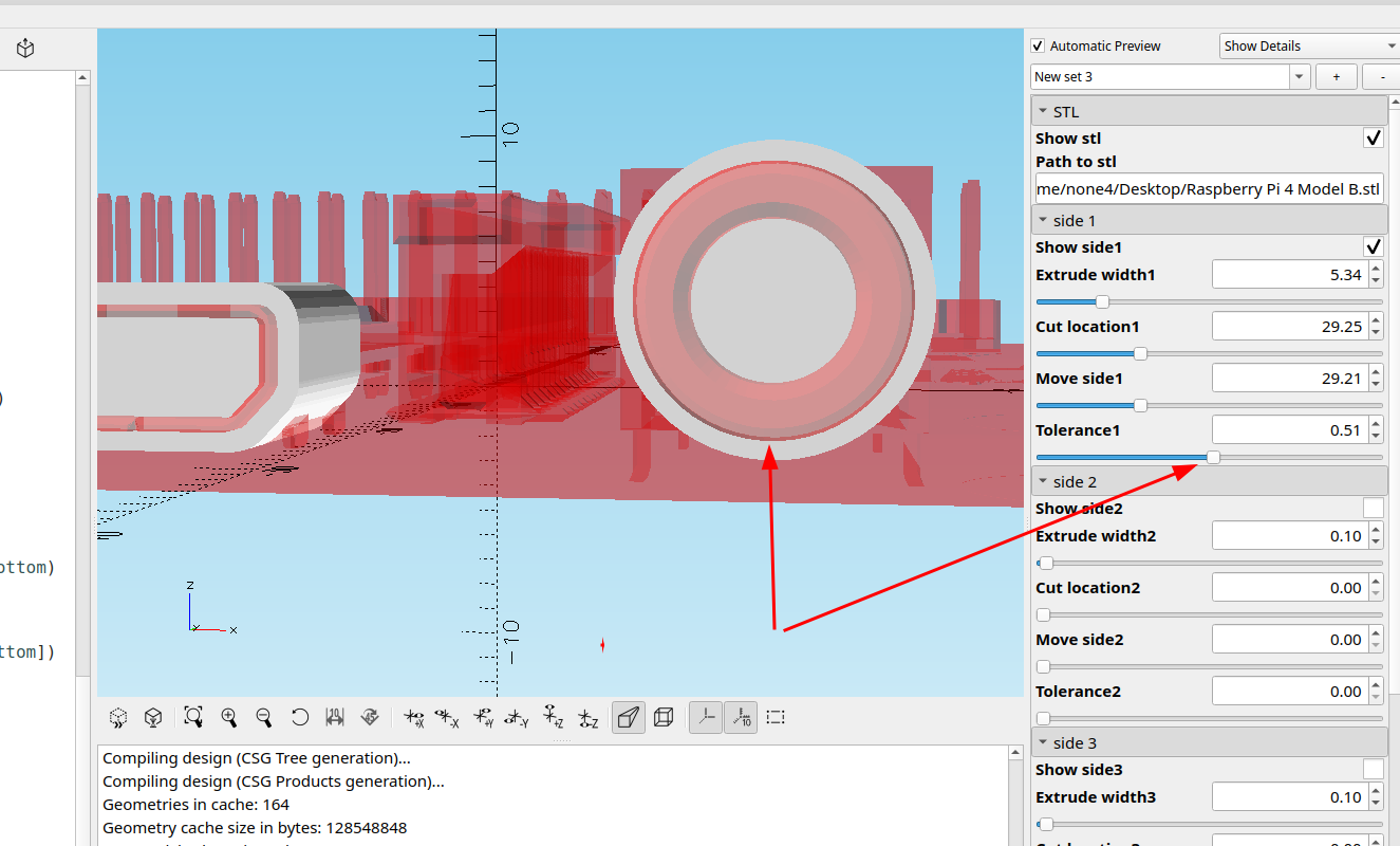
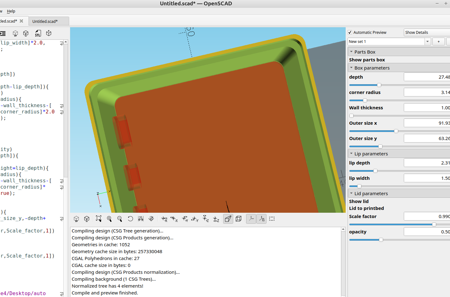
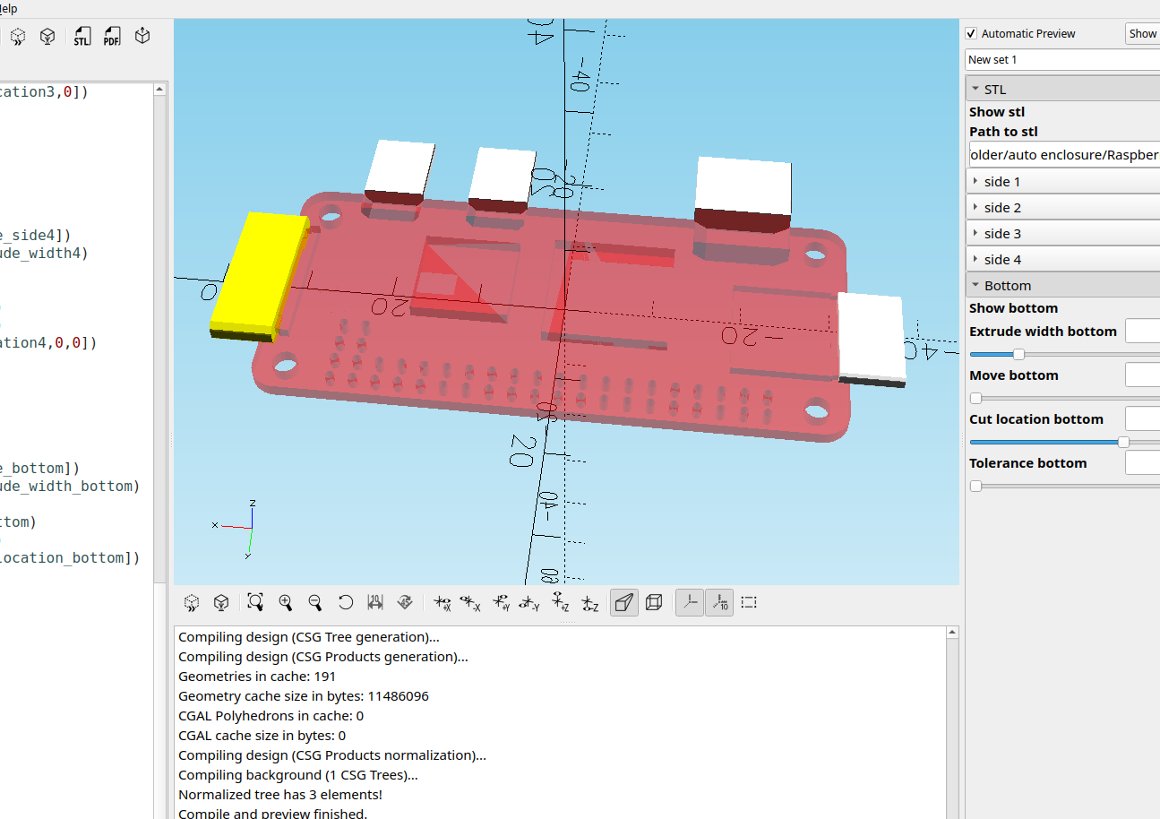
Once you get the cut location where you want it you can adjust the tolerance around the cut outs to make more space for plugs:
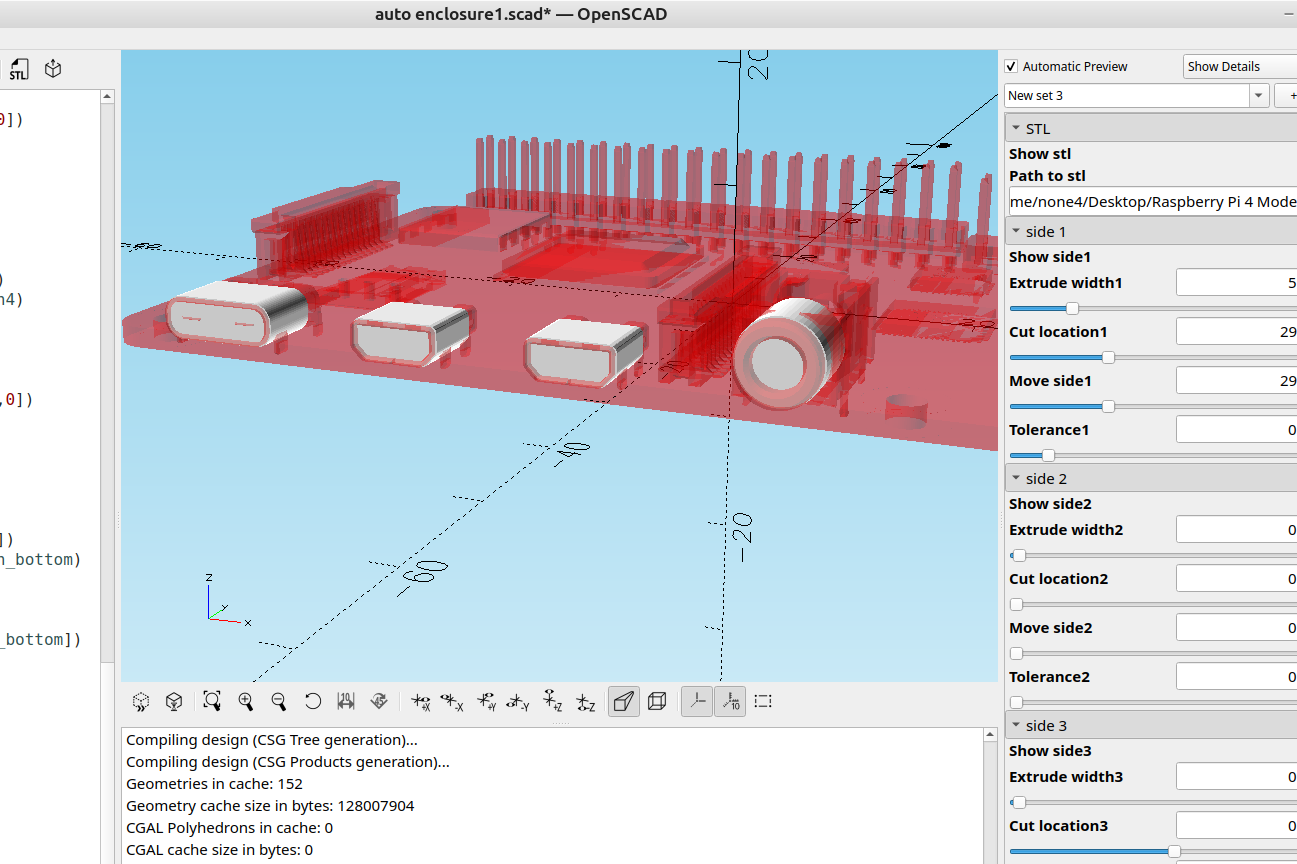
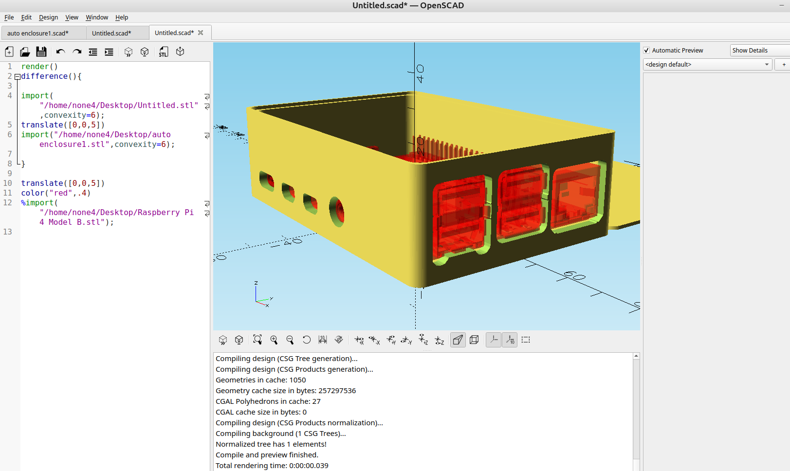
With the stl file in red and the cut outs in white it's easy to see how much space will be around them.
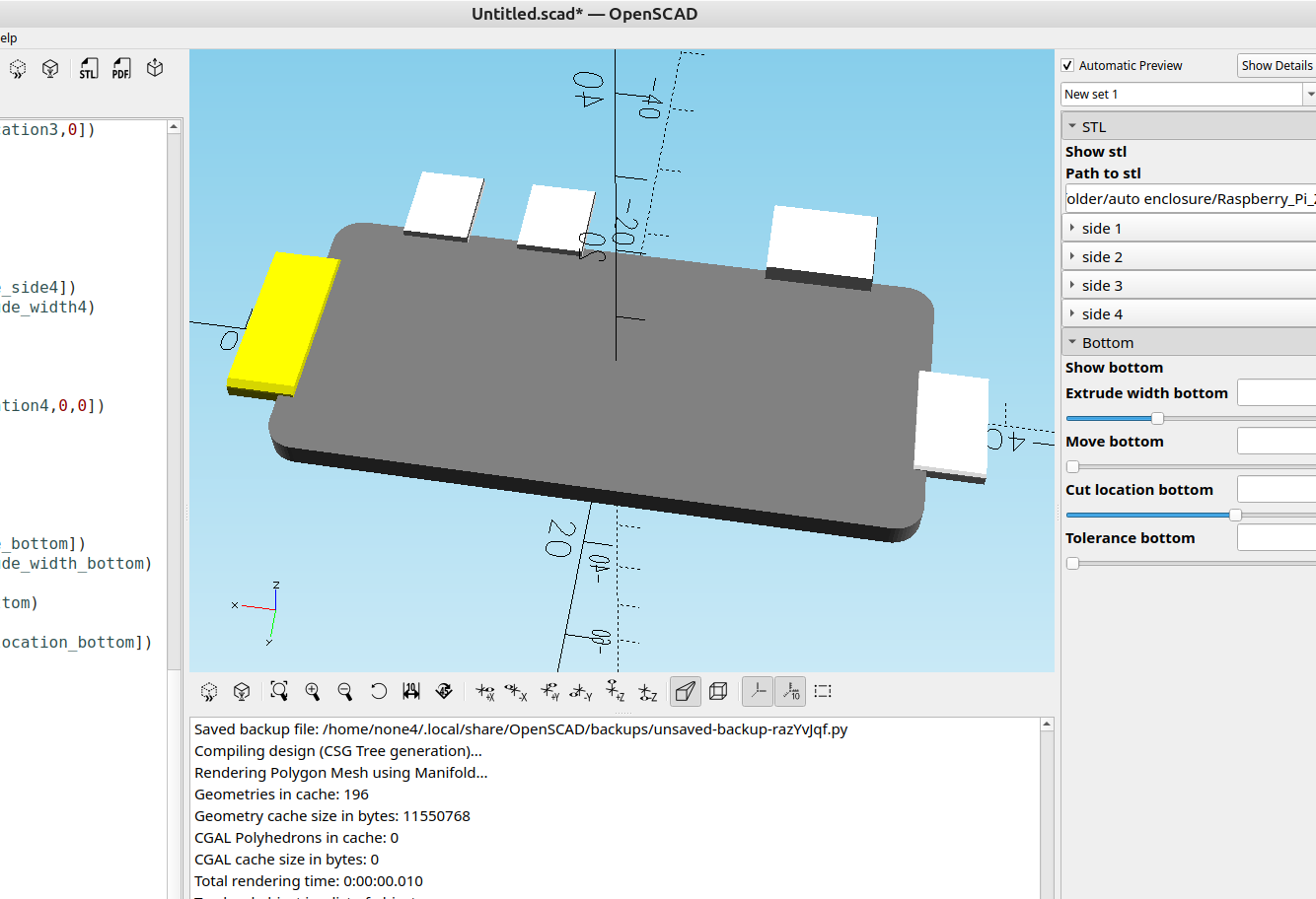
I got it set up for the 4 sides and the bottom, I didn't add a module for the top because I haven't needed it yet but it will be pretty easy to add.
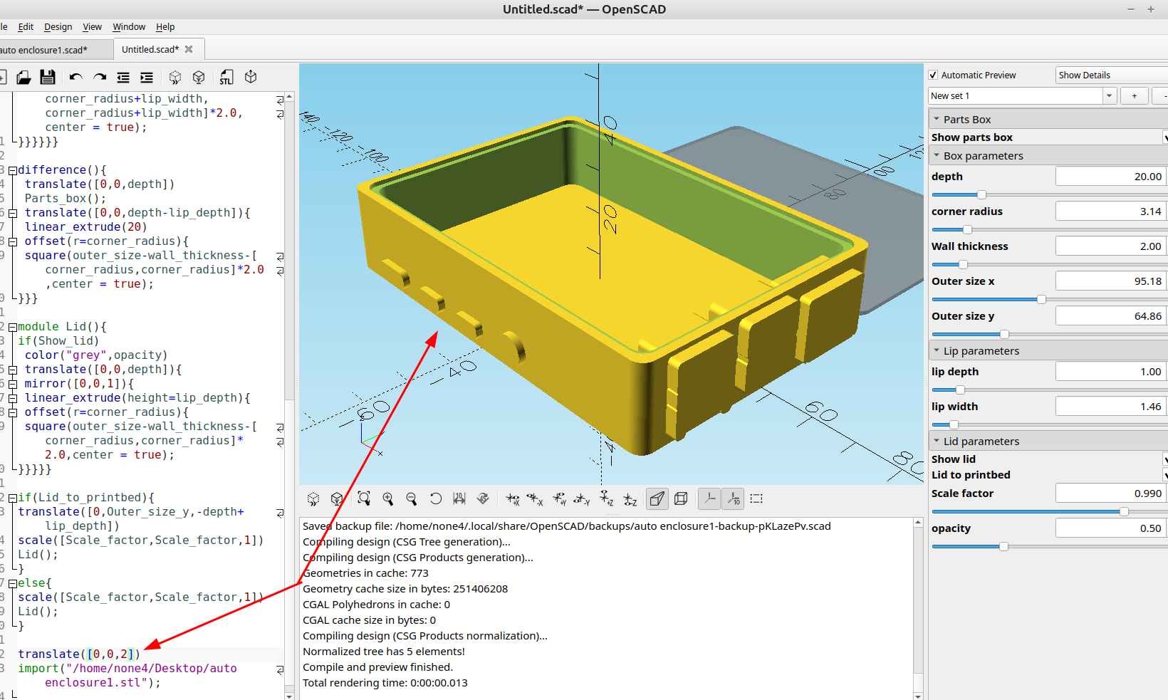
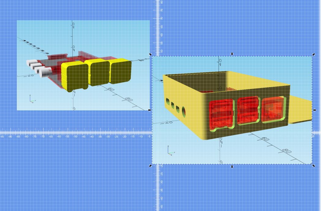
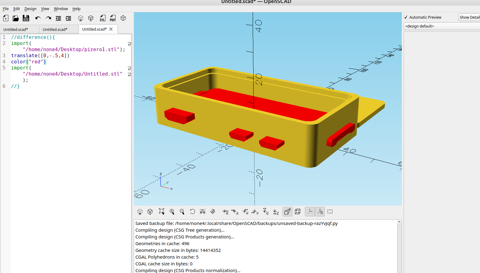
Once the ports are where you want them you can export the stl and import it into the enclosure maker I made in post #111 and adjust the size and corners to fit the board:
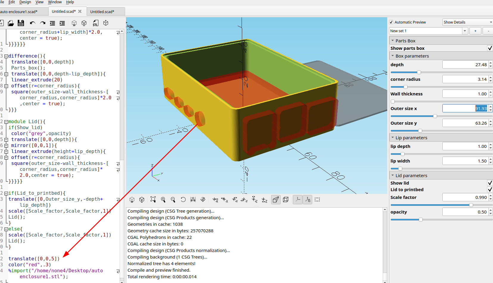
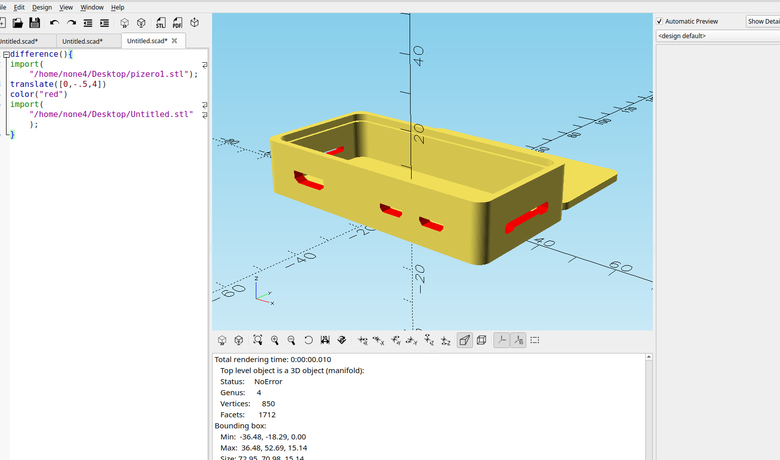
Then the box can be saved and both the helper board and the box can "differenced" from each other:
And for a Pi Zero:
Eventually I will add the capability to save each port as an stl file so they can be used with any design.