
3D part design with Inkscape and OpenSCAD #99: STL to CNC part 2, using multiple layers with gcodetools.
In the last post I set up a basic svg file as an introduction to the gcode tools extension , in this post I'm going to set up a template with multiple layers so it can be used to make different cut depths for different layers and engraving.
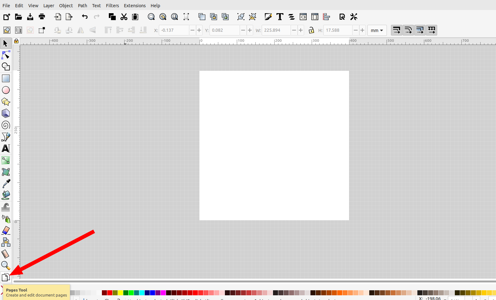
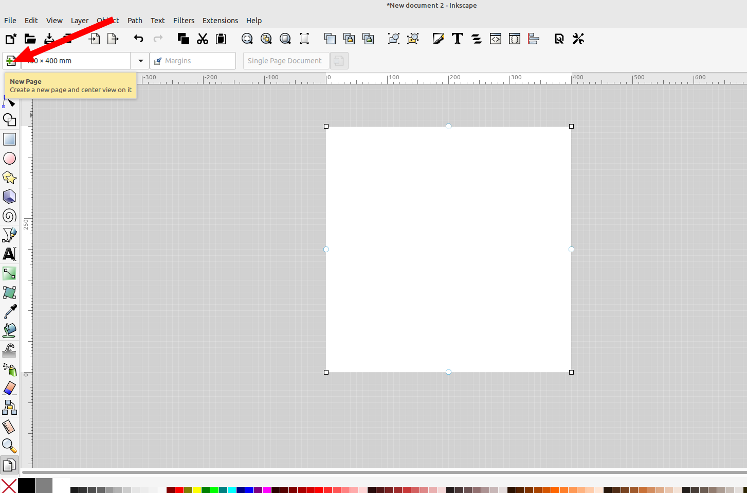
This time I'm going to use multiple pages in Inkscape by clicking on the page tool and adding another page:
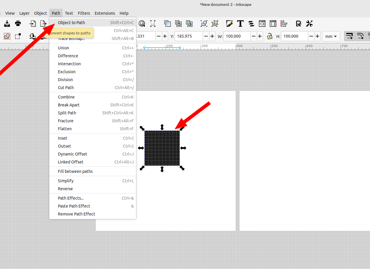
Then I'm going to add a square on layer 1 that is 100mm x 100mm and convert it to a path:
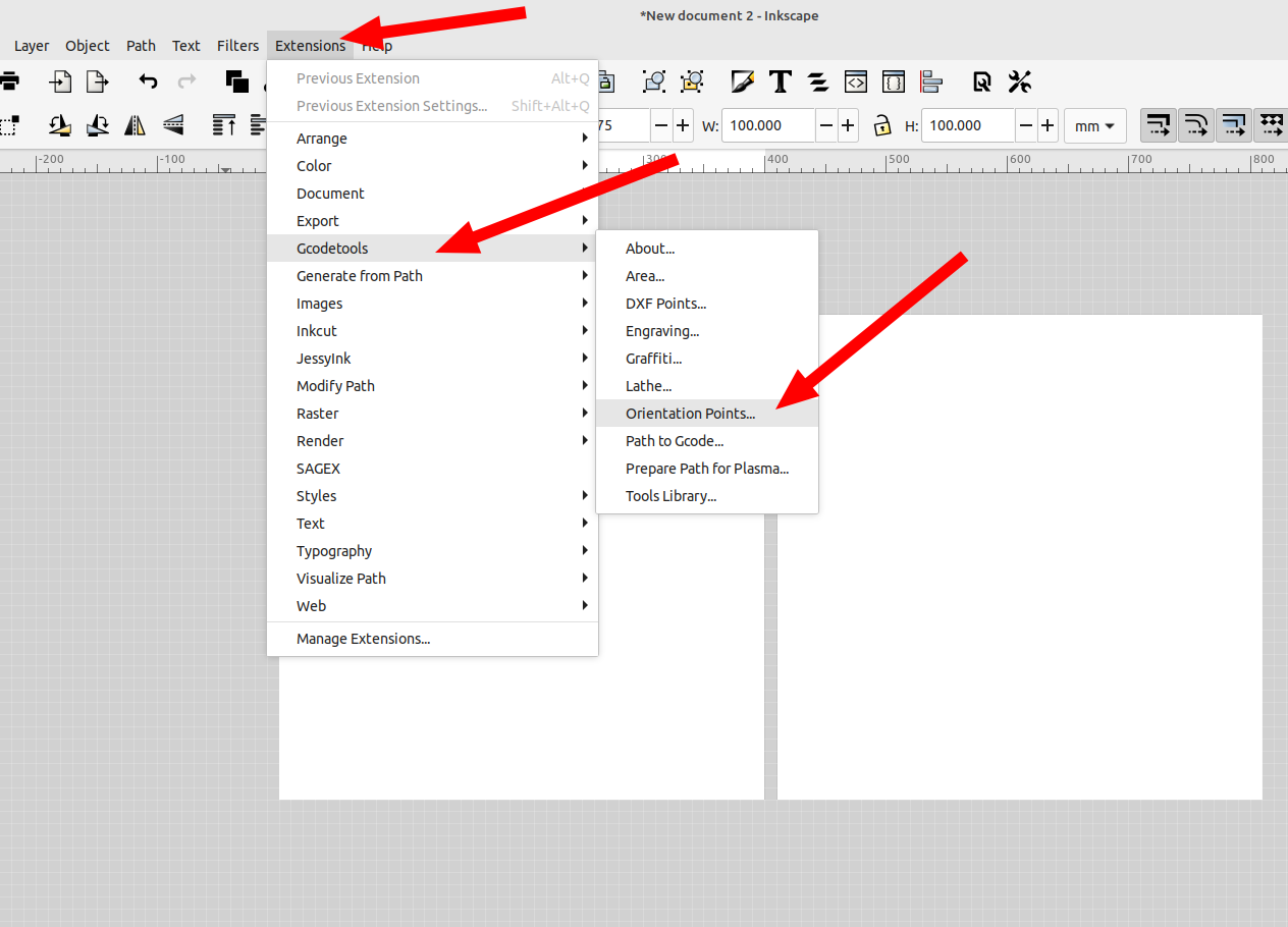
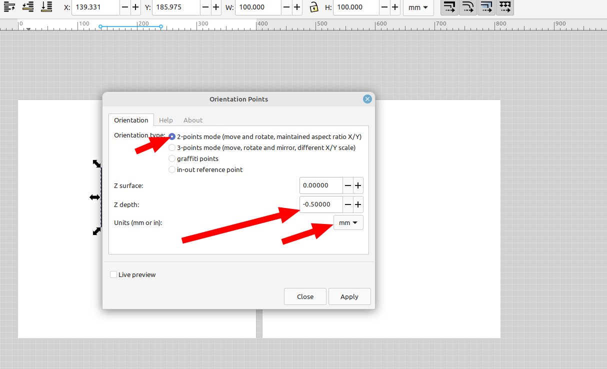
Then I'm going to go to the gcode tools extension and select orientation points and click apply:
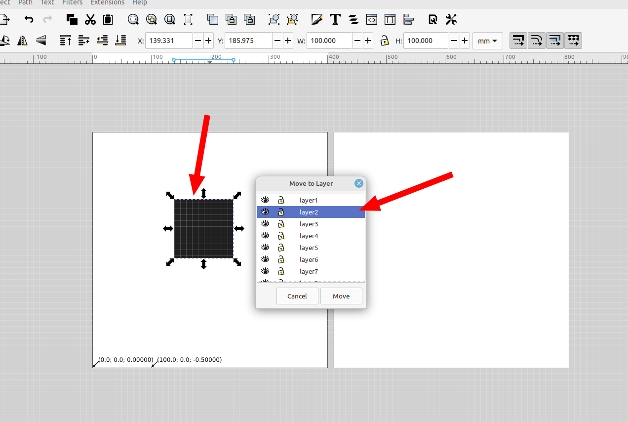
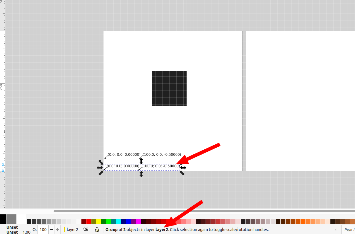
Now the orientation points for the object will be set on layer 1, next I will select the square and move it to layer 2:
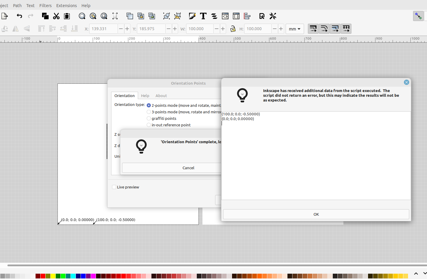
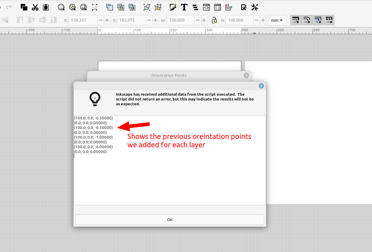
Then open the gcode tools extension and add orientation points for it again on layer 2, you will see the previous points we added for layer one in the dialog box that pops up:
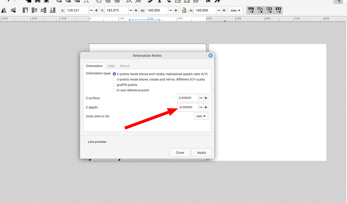
Now I'm going to select the square again and do the same thing for layers 3, 4 and 5 but change the depth setting to the depth I want that layer to cut to (the thickness of the material I am cutting):
I did this so I can make holes or cut out the final shape with the outline I make on those layers.
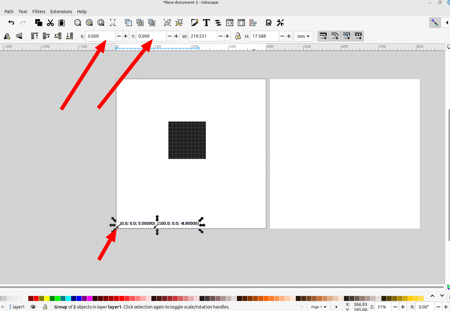
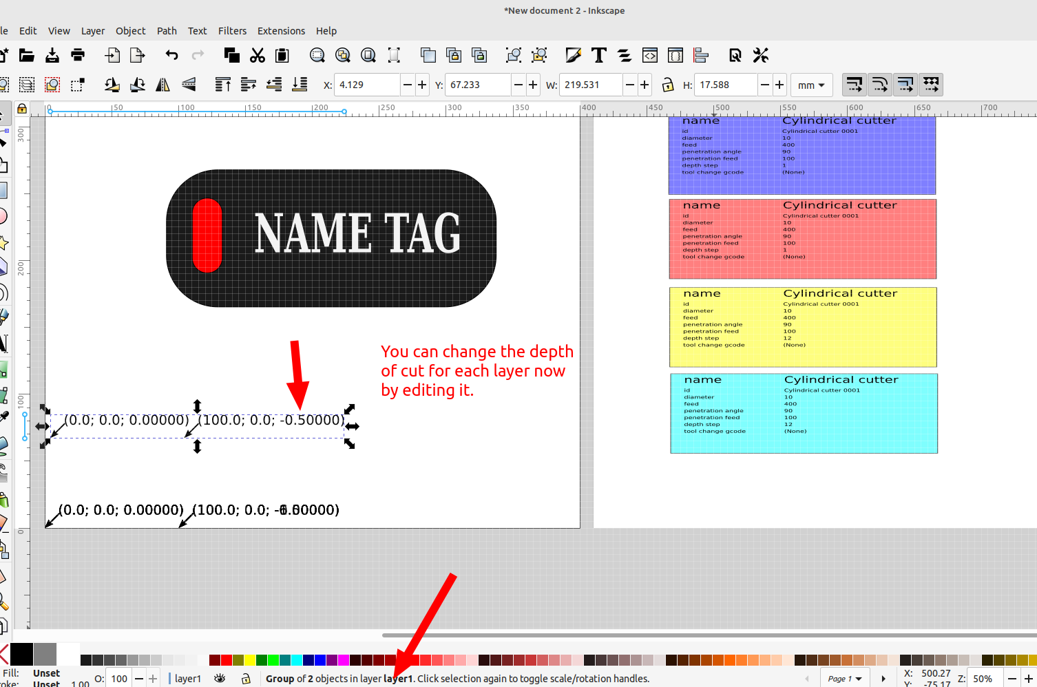
If you get an error message during this process you probably forgot to make the shape a path with Path> object to path. You will notice that the text that is created for the different orientation points overlap each other at the bottom of the page, you can change the cut depth by editing the text then making sure the text is set back at (0,0)
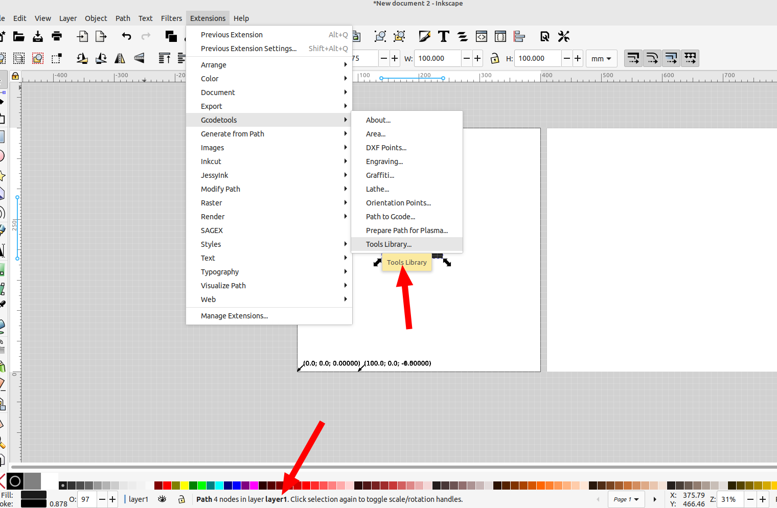
Next we are going to add a tool for each layer by selecting Extensions>GcodeTools>Tools Library. Make sure the square is moved to layer 1 for the first one:
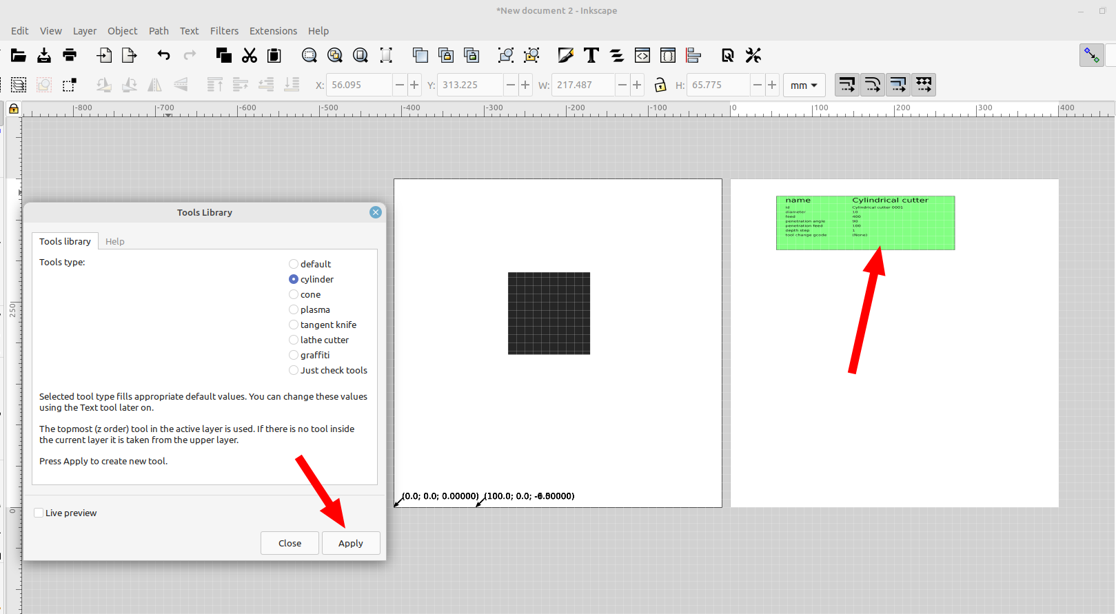
Select the tool type you want and a green object with the tool parameters will be made, I resized it so I will be able to fit five tool configs on the new page I made earlier
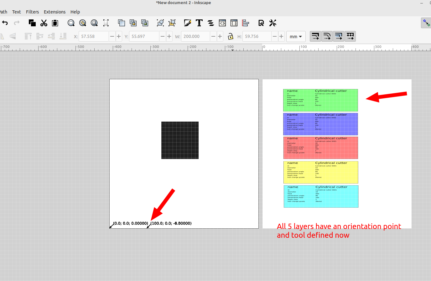
Now do the same thing for the different layers you want to add, making sure to move the square to a new layer each time, you'll notice the new tool parameters will be a different color so you can tell it's a new tool.
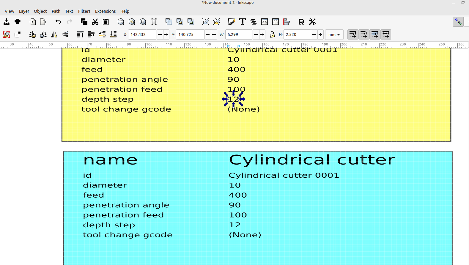
Set the parameters for each layer based on your cnc, the tool diameter is important for engraving and depth step for multiple cutting passes:
Now I am going to add the shape I want to cut out on layer 5, a slot on layer 4, and a name on layer one that will be engraved, select them all and convert them to paths:
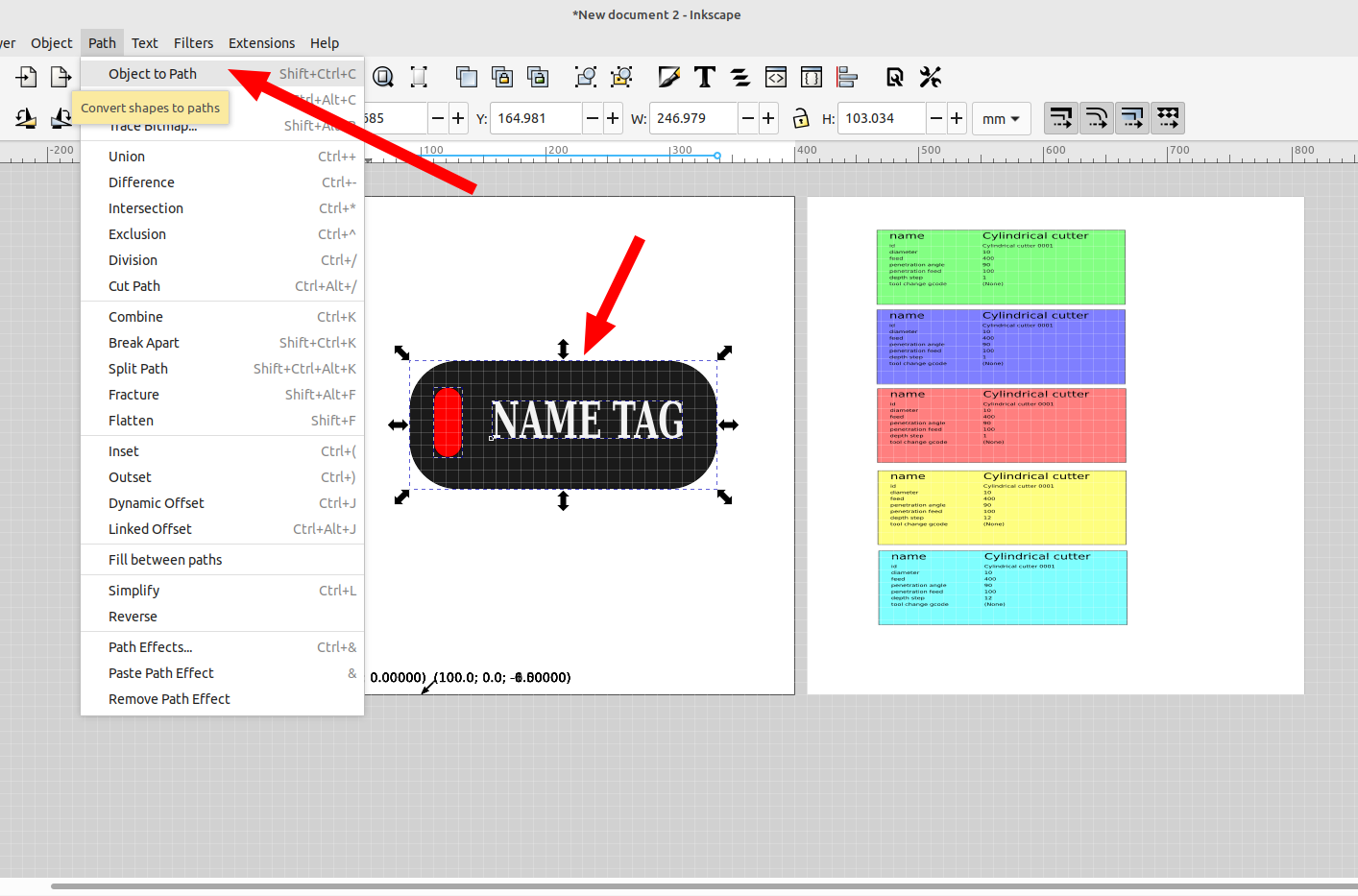
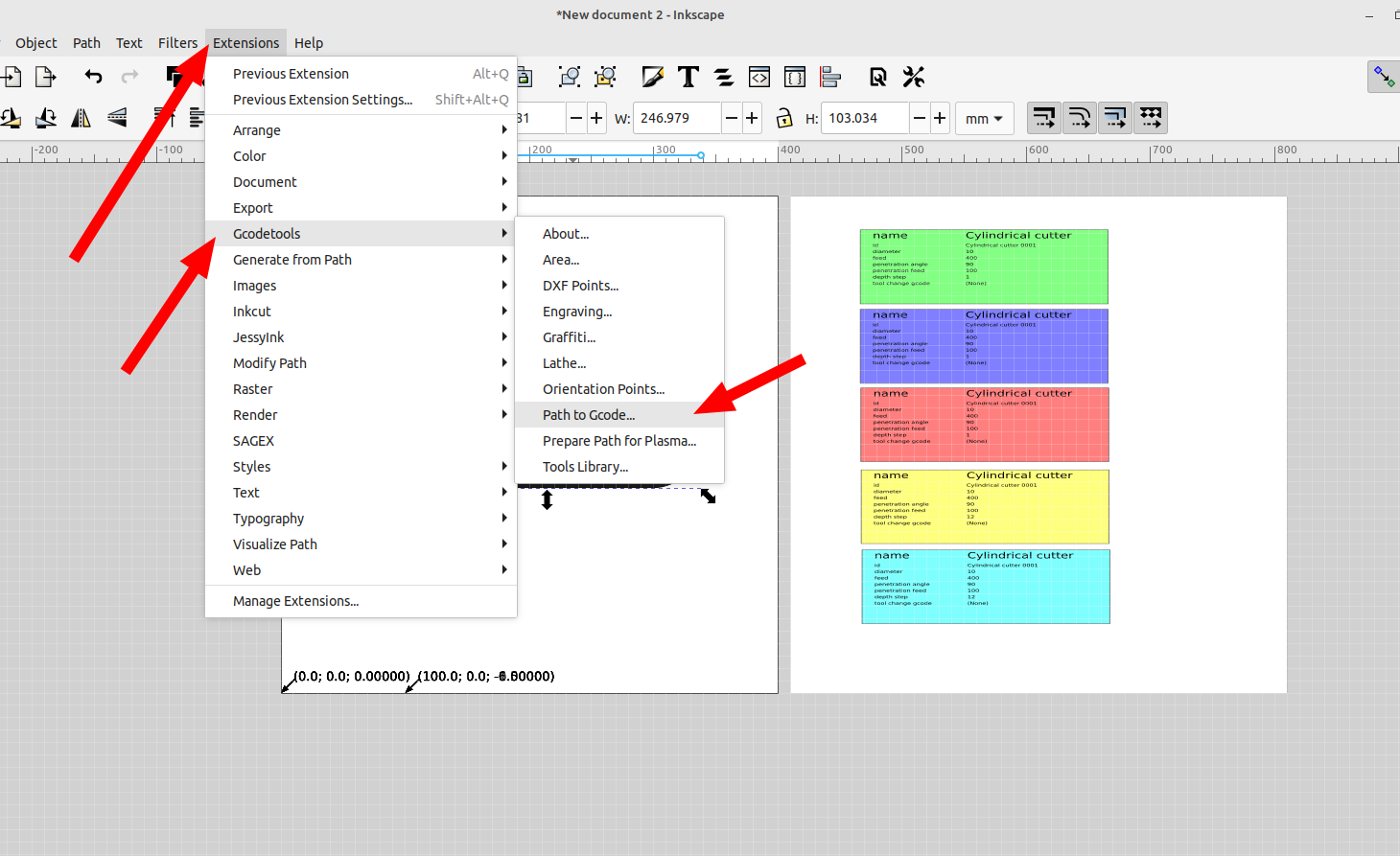
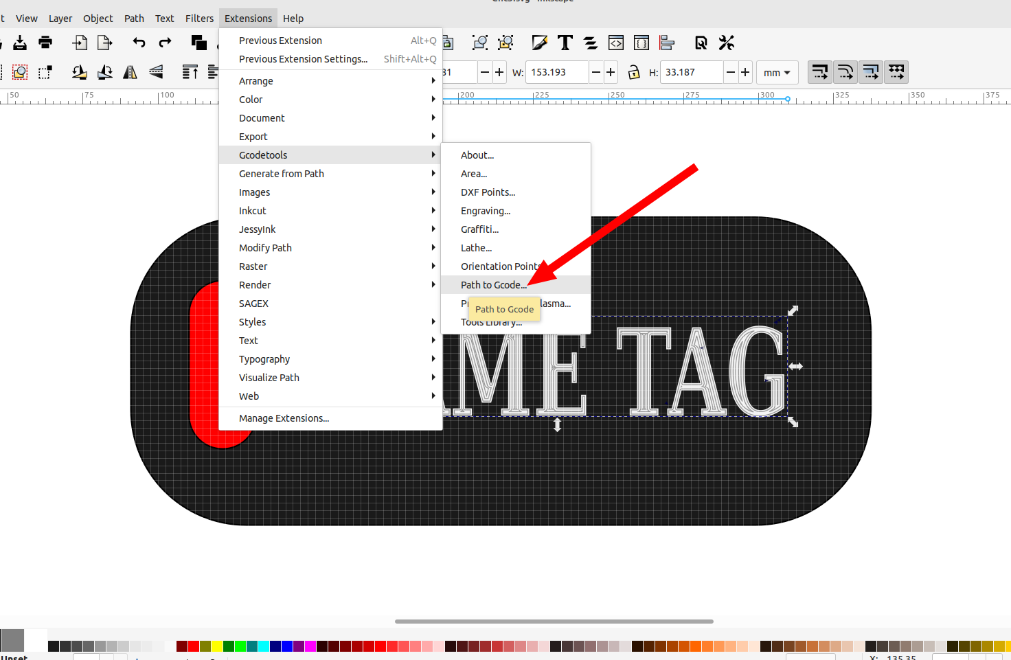
Go to Extensions>Gcodetools> Path to Gcode
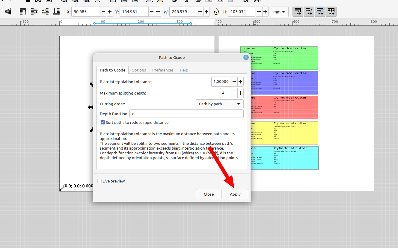
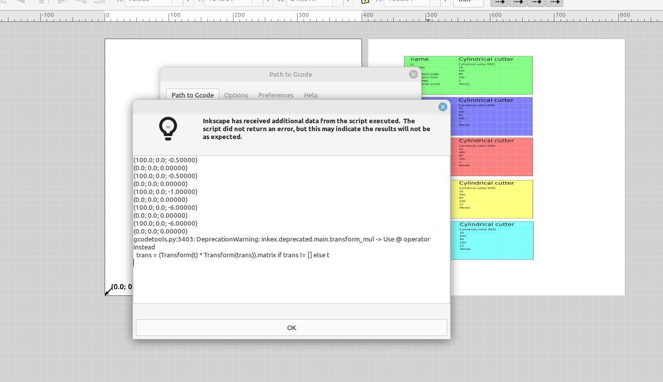
A dialog pops up showing the orientation points for the layers that were successfully exported, and a message telling me gcode tools is using outdated syntax, this doesn't have any effect on the gcode file that is exported that I can tell.
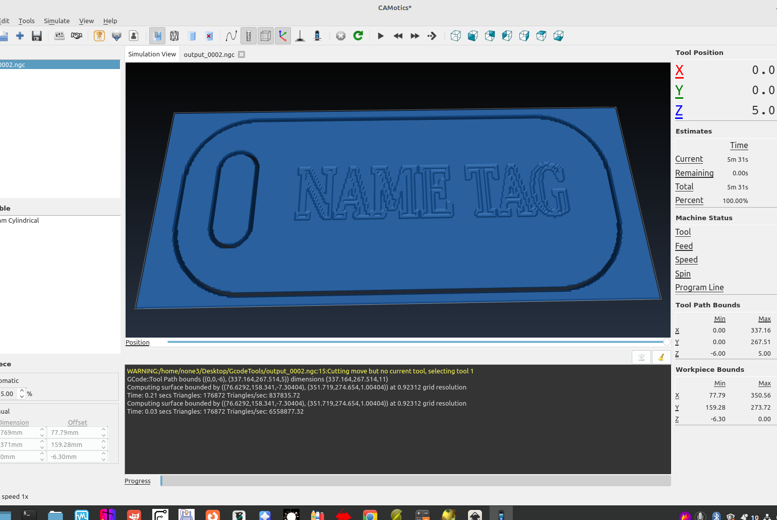
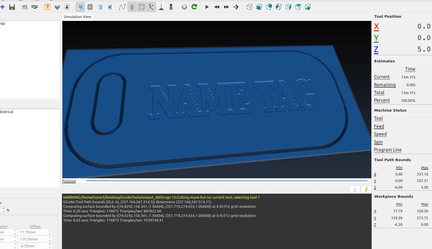
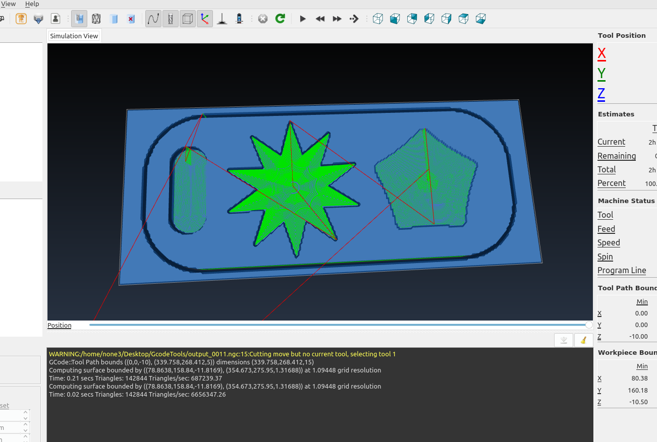
Now I can open the gcode file with camotics and see how it turned out, I have cuts all the way through for the outline and the slot and text engraved to - .6 mm depth:
The back side showing the cut is all the way through:
you can change the depth of each tool by editing it for that layer and then moving it back to (0,0)
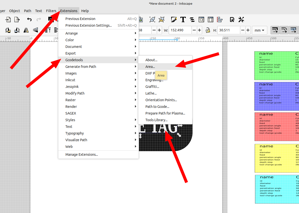
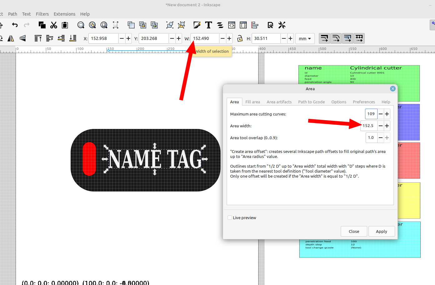
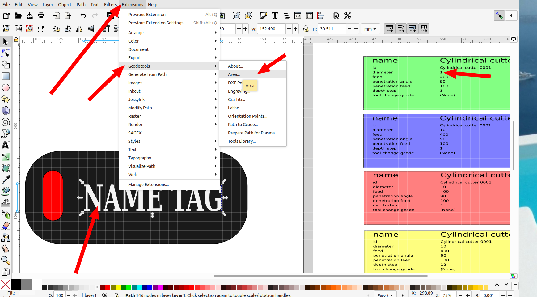
The outlined text was fine but what if I want to engrave the entire shape of the text? Gcodetools has an "Area" option, select the text and go to the area setting in gcodetools:
Set the area width to the width of the object. This where the diameter of the tool is important if it is too big the cut path that is generated will be all over the place so you will want to make sure you set it in the tool set up for that layer:
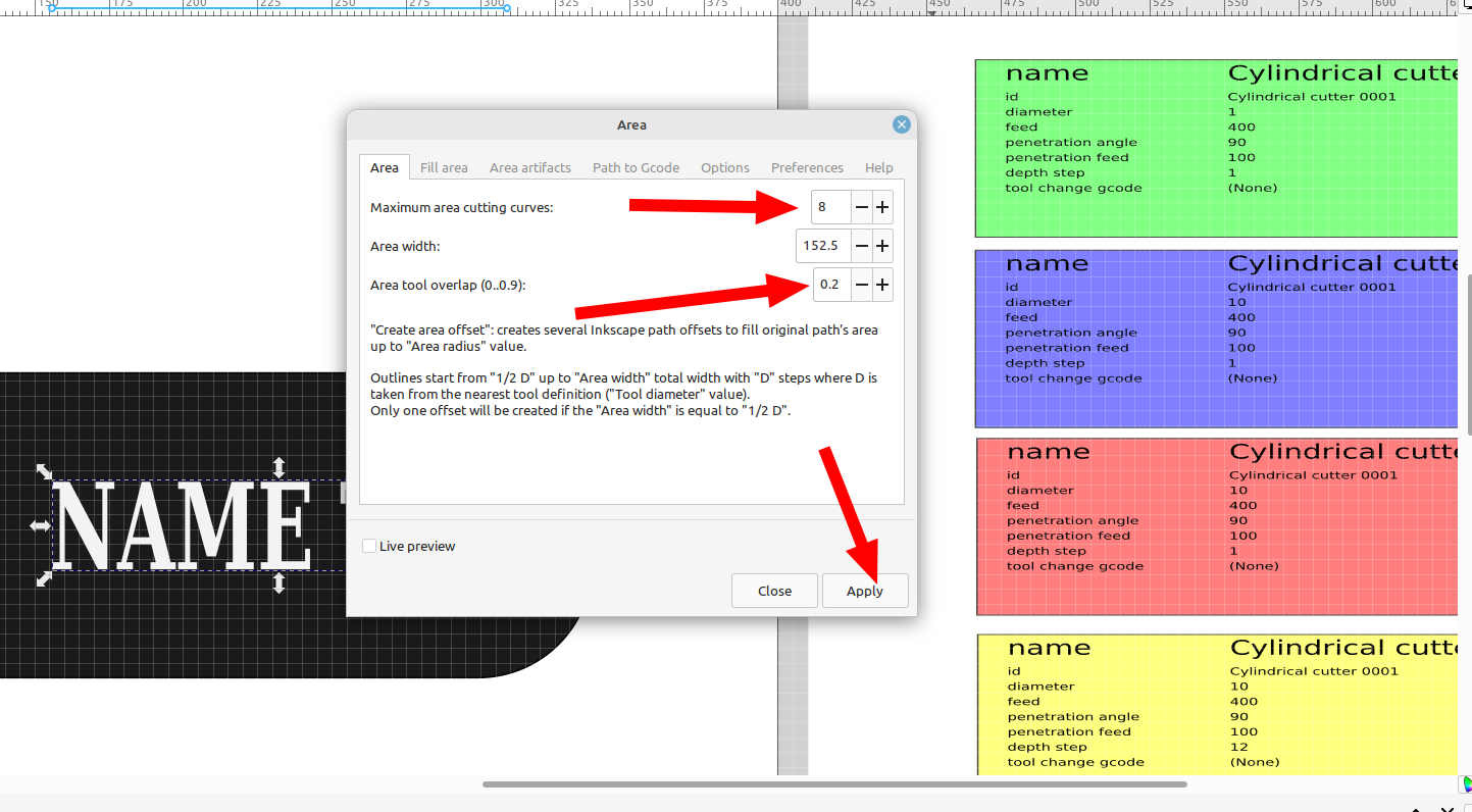
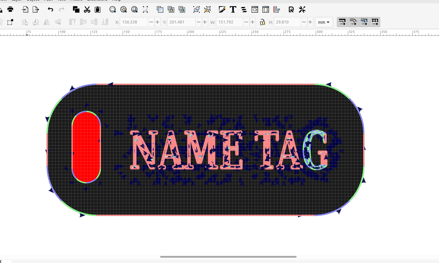
The maximum area cutting curves will need to be set according to the area inside the object you want to engrave so some experimentation will be needed, I set it to 8 for the lettering:
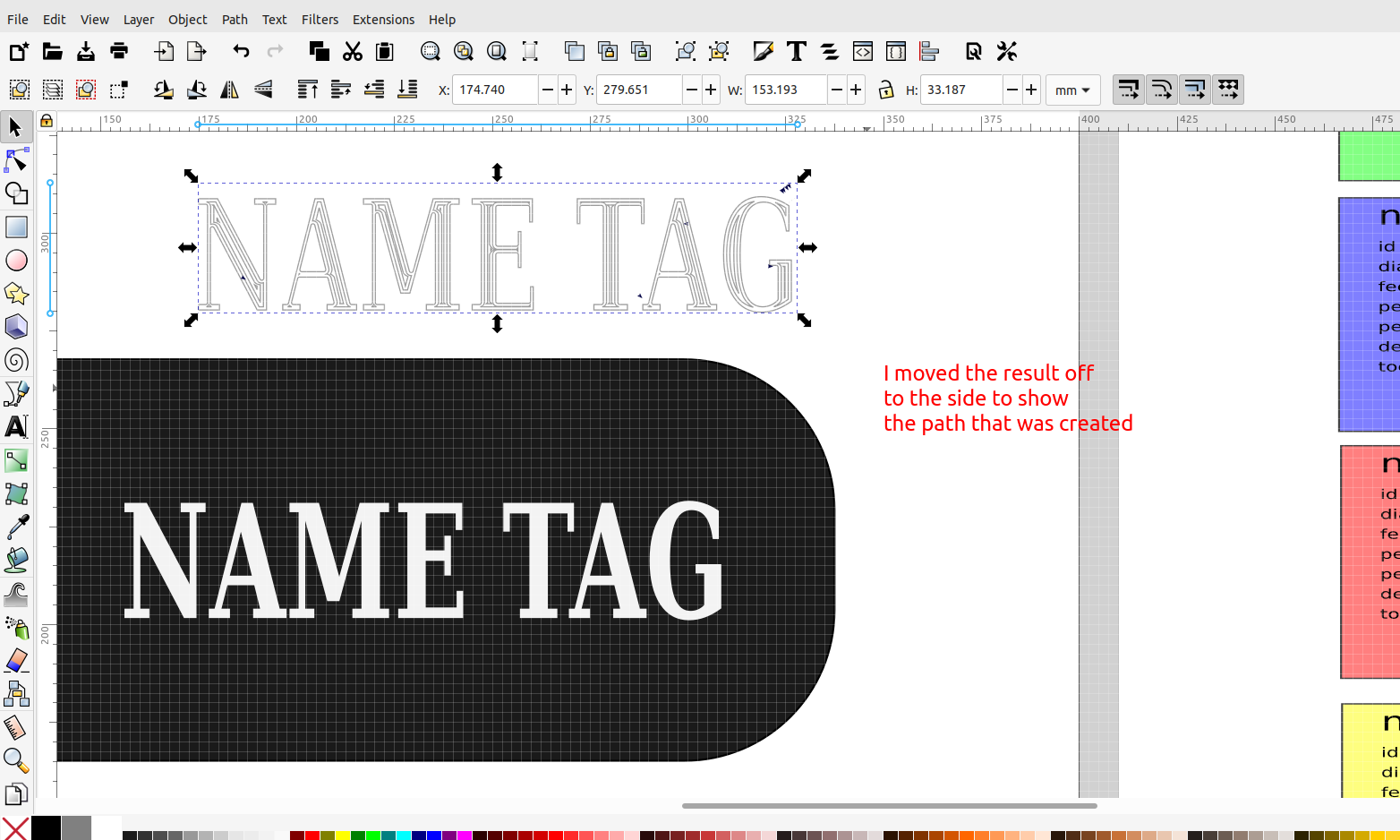
The path created should look nice and clean, if you have a bunch of artifacts the settings will need to be adjusted, usually it's the tool size and the number of cutting curves based on the size of the object.
Now you can go to gcode tools again and select path to gcode to export the gcode:
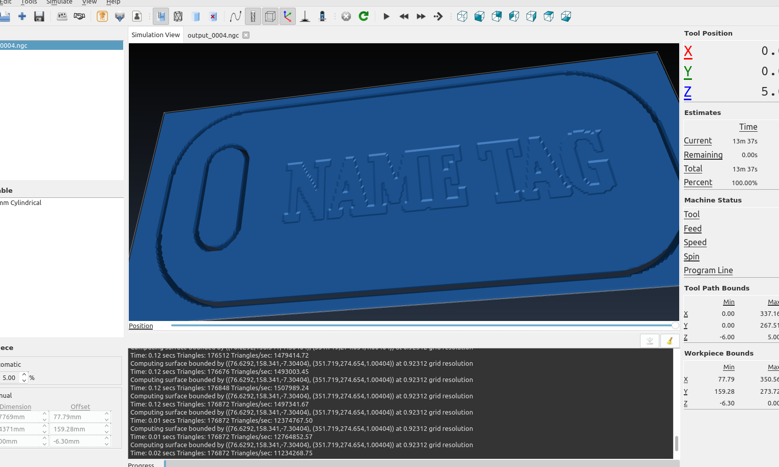
This time the area of the text is engraved down to - .6 , and the cut out and slot on layers 4 and 5 are set to cut all the way through
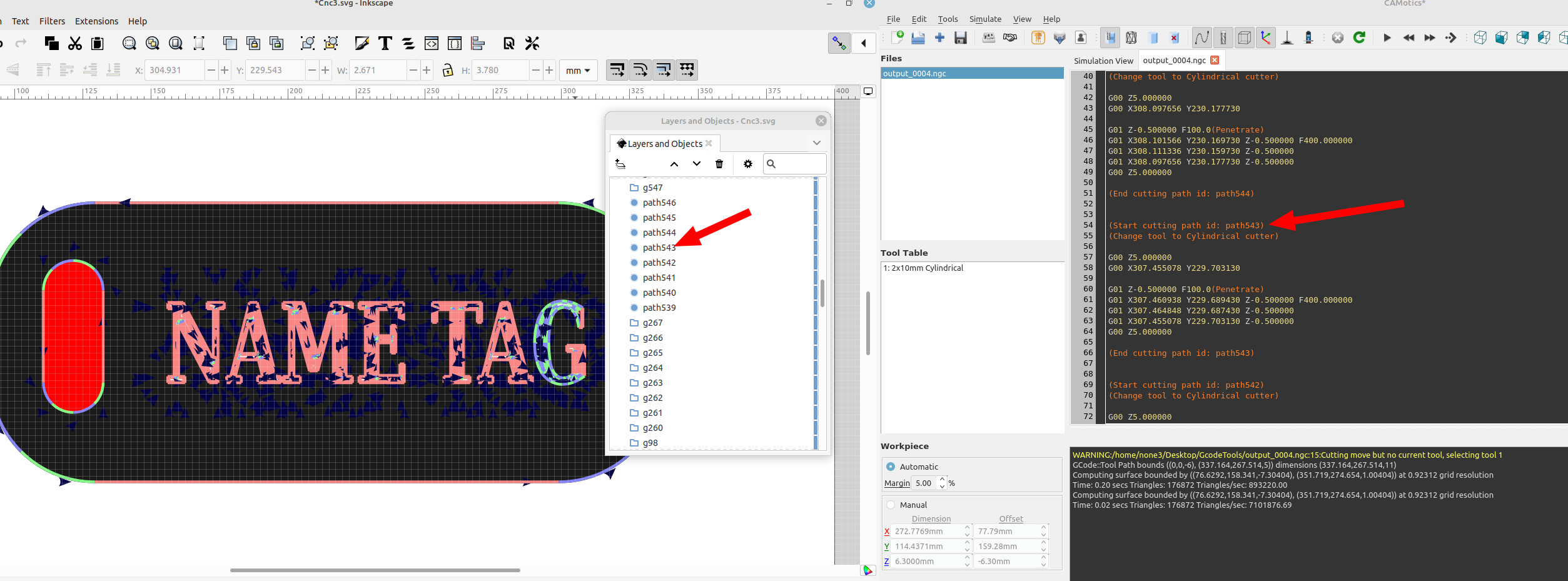
If you double click on the gcode file in camotics a gcode editor will be added and you can inspect the gcode:
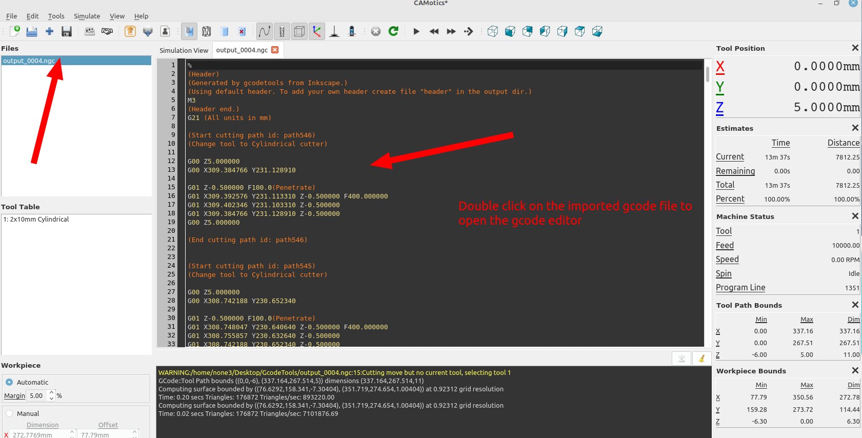
you can compare the gcode file to the layers in Inkscape and have the ability to edit your design down to very fine details:

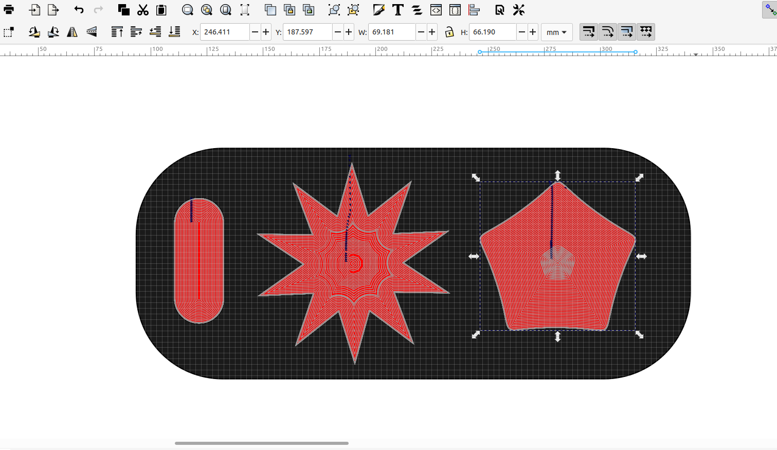
Here are 4 different objects on 4 different layers with 4 different cut depths:
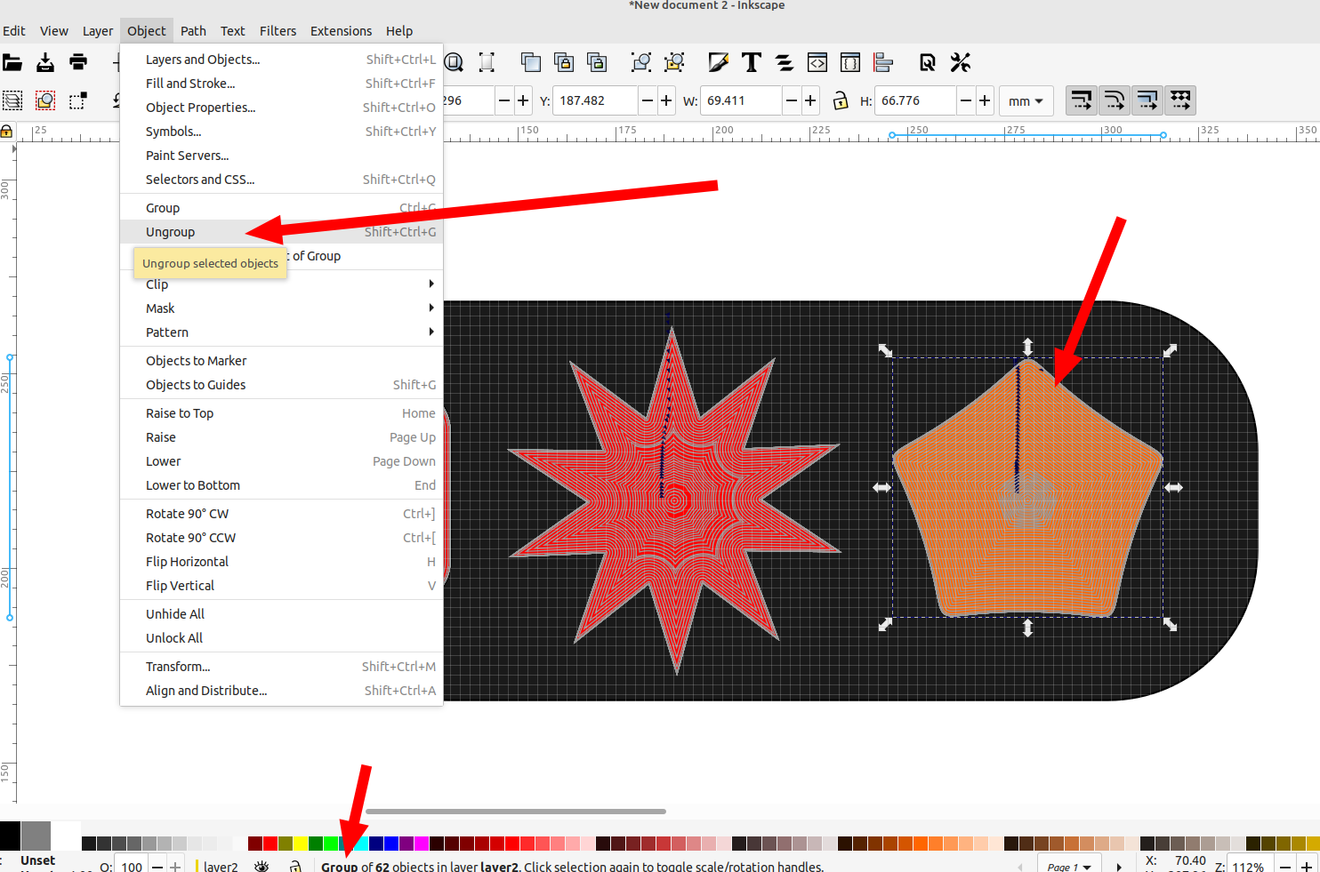
After you use the "area" tool in gcode tools make sure to ungroup the paths or it will generate an error when you try to export with "path to gcode"
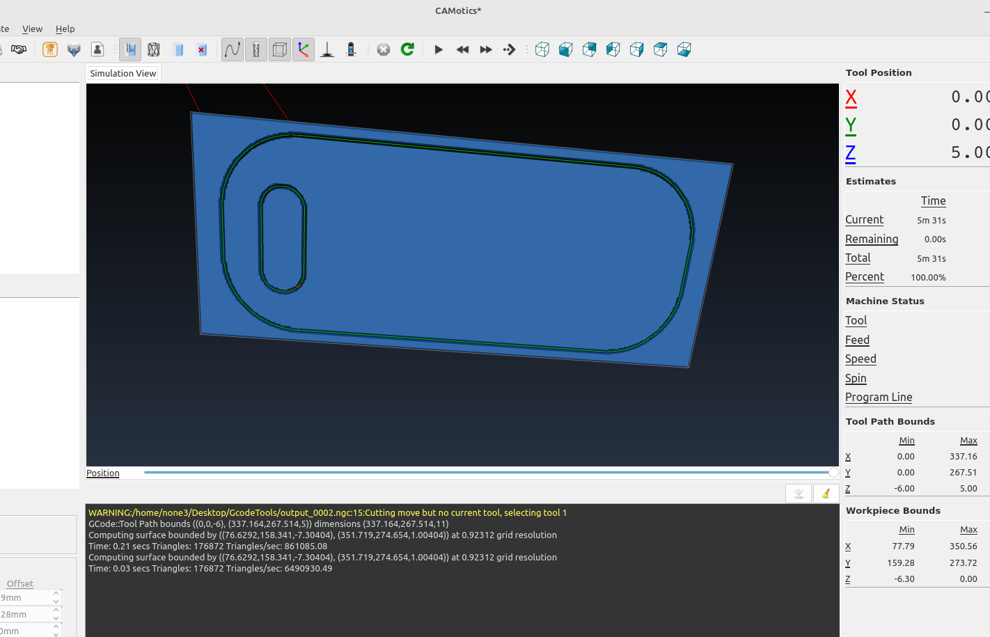
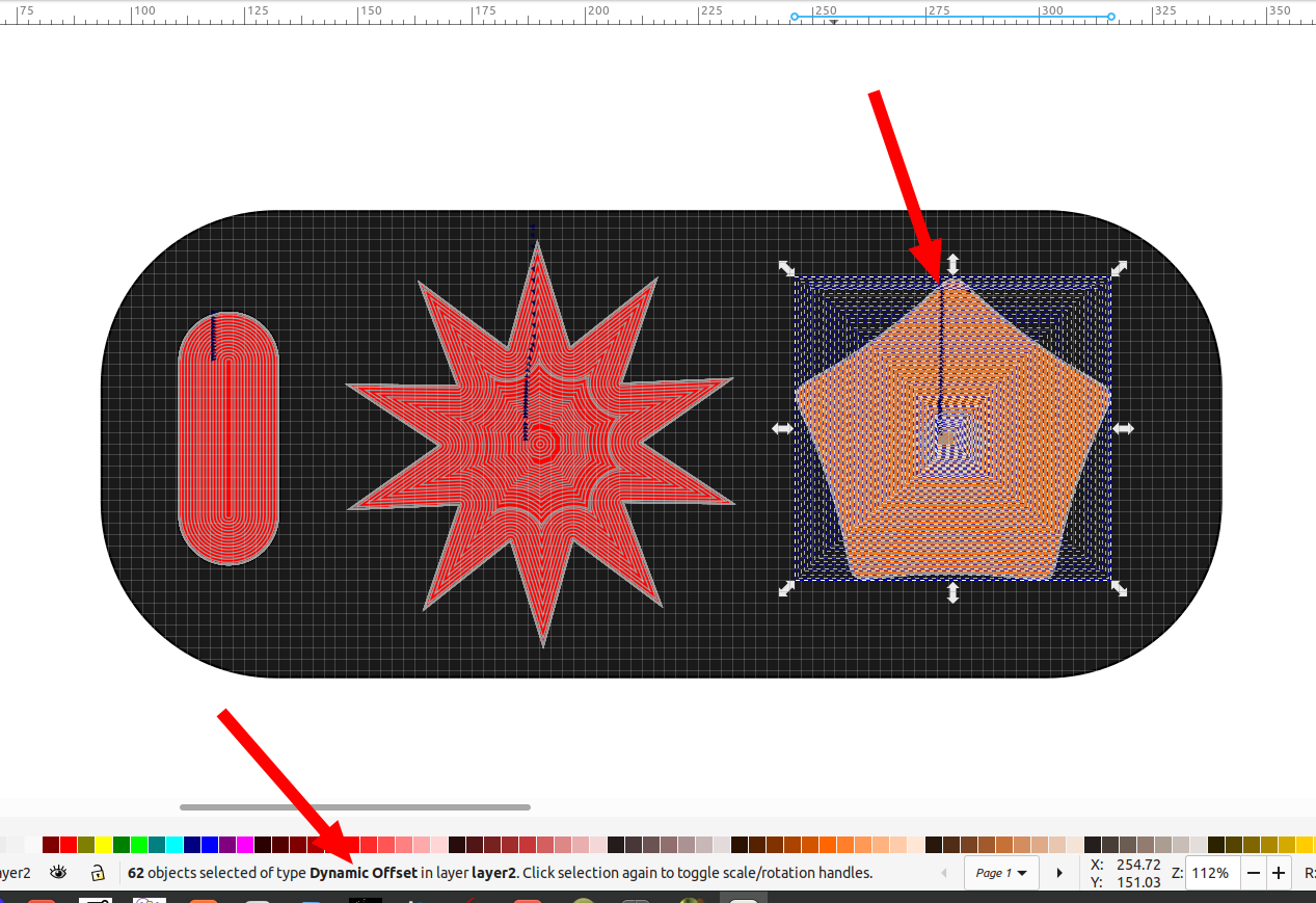
Showing the cut paths successfully ungrouped:
And after using path to gcode:
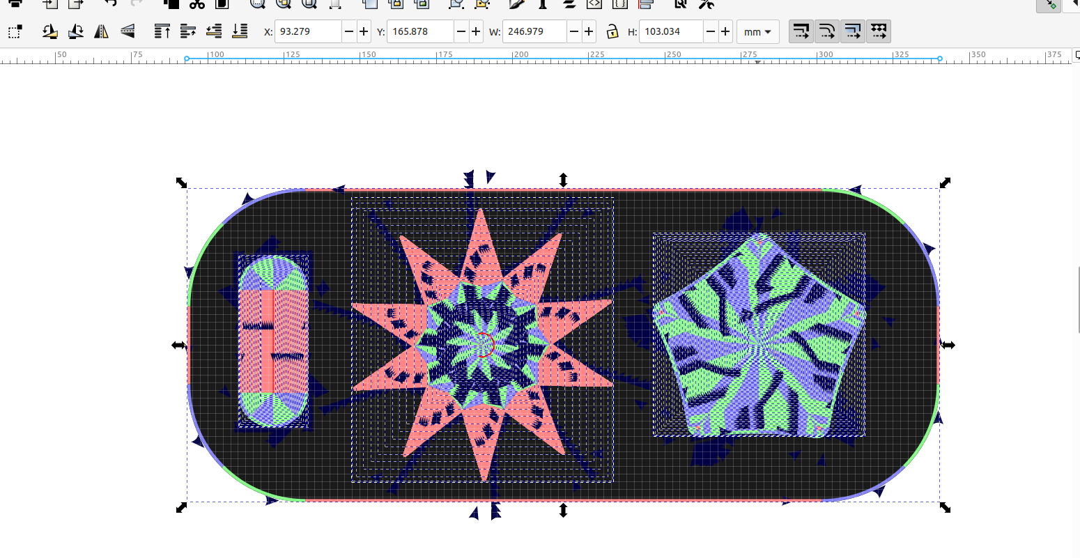
You can see the different objects ready to be cut out at different depths:
Now you can save the file in Inkscape as an svg file or a template and have everything set up where all you need to do is change some of the text for the orientation points and tool settings.