
3D part design with OpenSCAD #146: Using for loops to make a marking ruler
Sometimes it's helpful to use a for loop to automatically increment numbers, shapes or sizes. I wanted a marking ruler to do some hole layout in the top of a panel but I couldn't find anything locally so I made one in OpenSCAD and printed it out of some PET filament I made out of soda bottles.
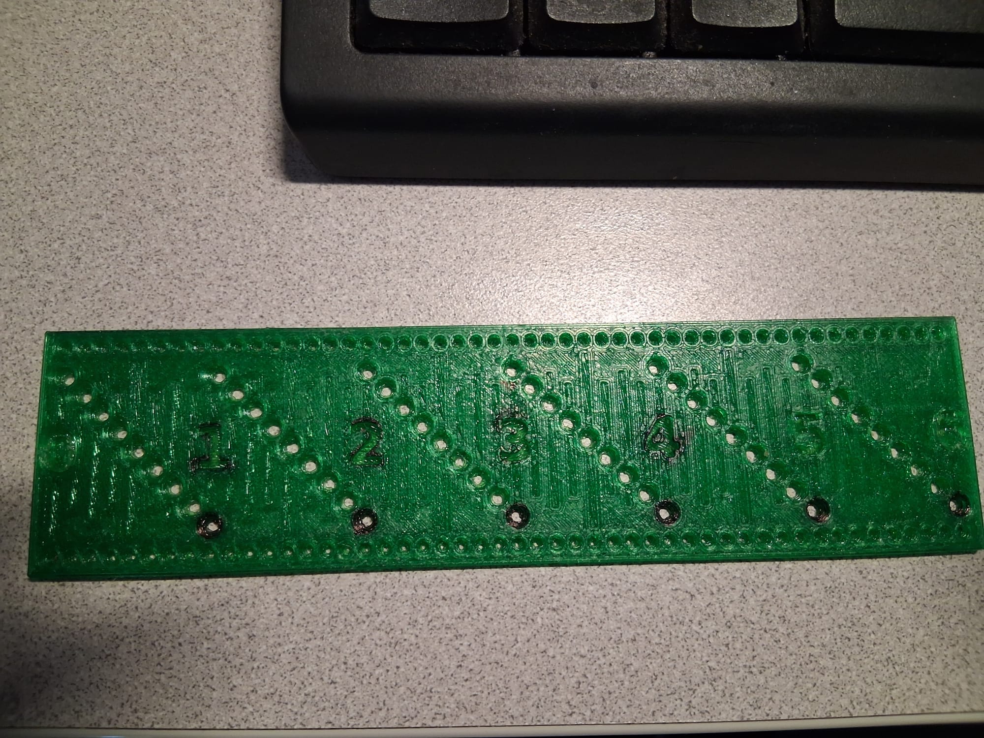
I made a few changes after I did this print, note the black marking is sharpie that I tried coloring in the numbers with but my sharpie is just about dried out. I also made the numbers and lines so they would print on the first layers so they will look good.
PET bottles make some really good filament. I highly recommend building or buying a pullstruder if you do a lot of printing, the price of free filament is hard to beat.
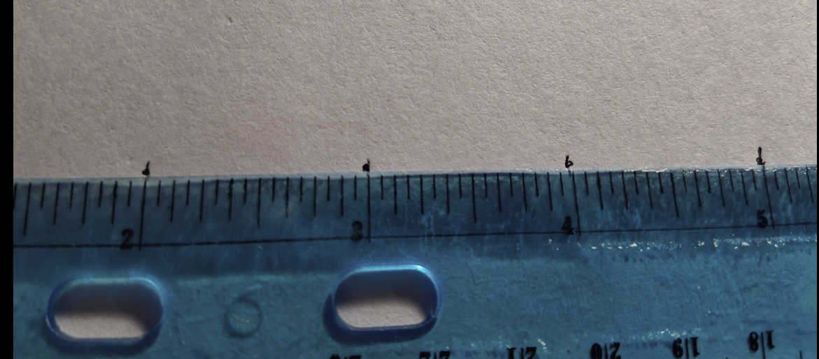
Is it accurate? Well according to the rulers I checked it with it is:
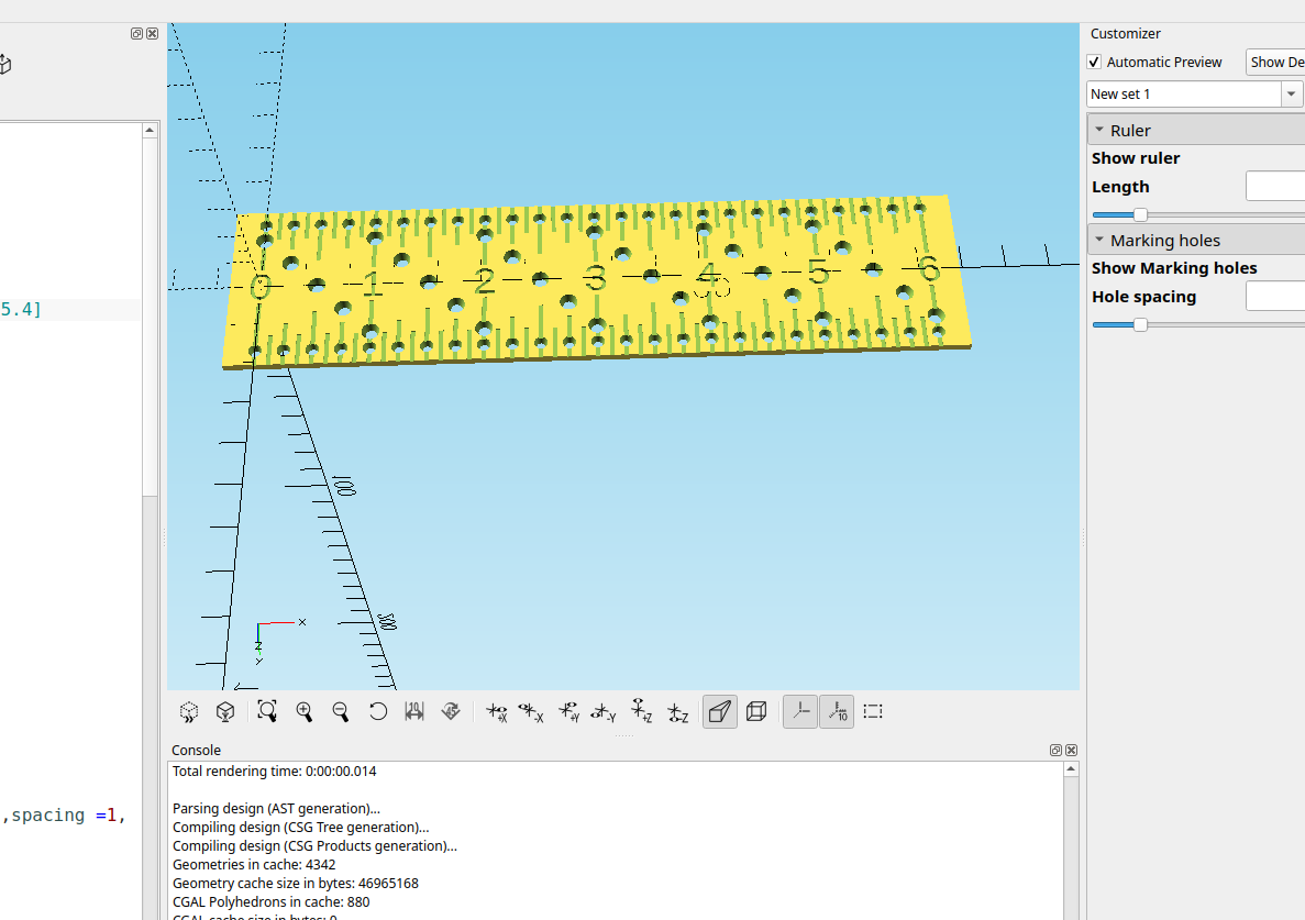
Here is the example code I made for the ruler:
//
/*[Ruler]*/
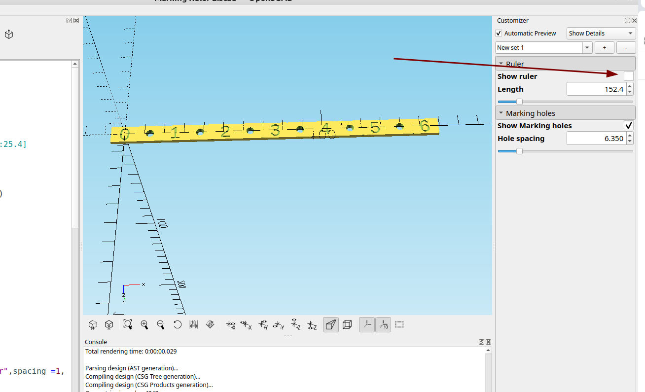
Show_ruler=true;
Length=152.4;//[25.4:25.4:914.4]
/*[Marking holes]*/
Show_Marking_holes=true;
Hole_spacing=3.1750;//[3.175:3.175:25.4]
module ruler(){
rotate([0,-90,0])
rotate([90,0,0])
translate([0,-Length-7,-20.6375])
cube([2,Length+14,41.275]);
}
module center_strip(){
rotate([0,-90,0]){
rotate([90,0,0])
translate([0,-Length-7,-4.5])
cube([2,Length+14,9]);
}}
module ruler_text(){
for(i=[0:Length/25.4]){
mirror([0,1,0])
translate([i*25.4,0,-1])
linear_extrude(2)
text(str(i),size=7,font ="",
halign="center", valign="center",spacing =1,
direction="ltr",$fn=100);
}}
module center_holes(){
for(l=[0:25.4:Length-3]){
for(j=[0:Hole_spacing:25.4])
translate([j,j,0])
translate([l,-12.7,0])
cylinder(3,2,1,$fn=100);
}}
module side_holes(){
for(n=[0:Hole_spacing:Length]) {
translate([n,-17,0])
cylinder(4,1.5,.6,$fn=100);
translate([n,17,0])
cylinder(4,1.5,.6,$fn=100);
}}
module scale_lines(){
for(i=[0:25.4:Length]){
translate([i,0,0])
rotate([90,0,90])
cube([41.275,.6,1],center=true);
}
for(i=[0:12.70:Length]){
translate([i,16,0])
rotate([90,0,90])
cube([18,.6,1],center=true);
}
for(i=[0:6.35:Length]){
translate([i,16,0])
rotate([90,0,90])
cube([12,.6,1],center=true);
}
for(i=[0:3.175:Length]){
translate([i,18,0])
rotate([90,0,90])
cube([10,.6,1],center=true);
}}
render()
if(Show_ruler){
difference(){
ruler();
if(Show_Marking_holes){
center_holes();
side_holes();
}
center_strip();
scale_lines();
mirror([0,1,0])
scale_lines();
}}
render()
difference(){
center_strip();
ruler_text();
if(Show_Marking_holes)
center_holes();
}
Right now the ruler is in inches and I will add to this so it will also be metric, it will be pretty simple to do.
I did add a check box so you could print just the center strip to make circles, I will probably change the way the center holes are laid out, I thought putting them at an angle would make the holes fit better but after I added the side holes it looks like it wasn't necessary.
Anyway now that I have the basics figured out making modifications will be a breeze.